Capacitance
Common symbols | C |
|---|---|
| SI unit | farad |
Other units | μF, nF, pF |
| In SI base units | F = A2 s4 kg−1 m−2 |
Derivations from other quantities | C = charge / voltage |
| Dimension | M−1 L−2 T4 I2 |
| Articles about |
| Electromagnetism |
|---|
 |
Capacitance is the ratio of the amount of electric charge stored on a conductor to a difference in electric potential. There are two closely related notions of capacitance: self capacitance and mutual capacitance.[1]: 237–238 Any object that can be electrically charged exhibits self capacitance. In this case the electric potential difference is measured between the object and ground. A material with a large self capacitance holds more electric charge at a given potential difference than one with low capacitance. The notion of mutual capacitance is particularly important for understanding the operations of the capacitor, one of the three elementary linear electronic components (along with resistors and inductors). In a typical capacitor, two conductors are used to separate electric charge, with one conductor being positively charged and the other negatively charged, but the system having a total charge of zero. The ratio in this case is the magnitude of the electric charge on either conductor and the potential difference is that measured between the two conductors.
The capacitance is a function only of the geometry of the design (e.g. area of the plates and the distance between them) and the permittivity of the dielectric material between the plates of the capacitor. For many dielectric materials, the permittivity and thus the capacitance, is independent of the potential difference between the conductors and the total charge on them.
The SI unit of capacitance is the farad (symbol: F), named after the English physicist Michael Faraday. A 1 farad capacitor, when charged with 1 coulomb of electrical charge, has a potential difference of 1 volt between its plates.[2] The reciprocal of capacitance is called elastance.
Self capacitance[]
In electrical circuits, the term capacitance is usually a shorthand for the mutual capacitance between two adjacent conductors, such as the two plates of a capacitor. However, for an isolated conductor, there also exists a property called self capacitance, which is the amount of electric charge that must be added to an isolated conductor to raise its electric potential by one unit (i.e. one volt, in most measurement systems).[3] The reference point for this potential is a theoretical hollow conducting sphere, of infinite radius, with the conductor centered inside this sphere.
Mathematically, the self capacitance of a conductor is defined by

where
- q is the charge held on the conductor,
- is the electric potential,
- σ is the surface charge density.
- dS is an infinitesimal element of area on the surface of the conductor,
- r is the length from dS to a fixed point M on the conductor
- is the vacuum permittivity


Using this method, the self capacitance of a conducting sphere of radius R is:[4]

Example values of self capacitance are:
- for the top "plate" of a van de Graaff generator, typically a sphere 20 cm in radius: 22.24 pF,
- the planet Earth: about 710 µF.[5]
The inter-winding capacitance of a coil is sometimes called self capacitance,[6] but this is a different phenomenon. It is actually mutual capacitance between the individual turns of the coil and is a form of stray, or parasitic capacitance. This self capacitance is an important consideration at high frequencies: It changes the impedance of the coil and gives rise to parallel resonance. In many applications this is an undesirable effect and sets an upper frequency limit for the correct operation of the circuit.[citation needed]
Mutual capacitance[]
A common form is a parallel-plate capacitor, which consists of two conductive plates insulated from each other, usually sandwiching a dielectric material. In a parallel plate capacitor, capacitance is very nearly proportional to the surface area of the conductor plates and inversely proportional to the separation distance between the plates.
If the charges on the plates are +q and −q, and V gives the voltage between the plates, then the capacitance C is given by

which gives the voltage/current relationship

where dv(t)/dt is the instantaneous rate of change of voltage.
The energy stored in a capacitor is found by integrating the work W:

Capacitance matrix[]
The discussion above is limited to the case of two conducting plates, although of arbitrary size and shape. The definition does not apply when there are more than two charged plates, or when the net charge on the two plates is non-zero. To handle this case, Maxwell introduced his coefficients of potential. If three (nearly ideal) conductors are given charges , then the voltage at conductor 1 is given by


and similarly for the other voltages. Hermann von Helmholtz and Sir William Thomson showed that the coefficients of potential are symmetric, so that , etc. Thus the system can be described by a collection of coefficients known as the elastance matrix or reciprocal capacitance matrix, which is defined as:


From this, the mutual capacitance between two objects can be defined[7] by solving for the total charge Q and using .


Since no actual device holds perfectly equal and opposite charges on each of the two "plates", it is the mutual capacitance that is reported on capacitors.
The collection of coefficients is known as the capacitance matrix,[8][9][10] and is the inverse of the elastance matrix.

Capacitors[]
The capacitance of the majority of capacitors used in electronic circuits is generally several orders of magnitude smaller than the farad. The most common subunits of capacitance in use today are the microfarad (µF), nanofarad (nF), picofarad (pF), and, in microcircuits, femtofarad (fF). However, specially made supercapacitors can be much larger (as much as hundreds of farads), and parasitic capacitive elements can be less than a femtofarad. In the past, alternate subunits were used in old historical texts; "mf" and "mfd" for microfarad (µF); "mmf", "mmfd", "pfd", "µµF" for picofarad (pF); but are now considered obsolete.[11][12]
Capacitance can be calculated if the geometry of the conductors and the dielectric properties of the insulator between the conductors are known. A qualitative explanation for this can be given as follows.
Once a positive charge is put unto a conductor, this charge creates an electrical field, repelling any other positive charge to be moved onto the conductor; i.e., increasing the necessary voltage. But if nearby there is another conductor with a negative charge on it, the electrical field of the positive conductor repelling the second positive charge is weakened (the second positive charge also feels the attracting force of the negative charge). So due to the second conductor with a negative charge, it becomes easier to put a positive charge on the already positive charged first conductor, and vice versa; i.e., the necessary voltage is lowered.
As a quantitative example consider the capacitance of a capacitor constructed of two parallel plates both of area A separated by a distance d. If d is sufficiently small with respect to the smallest chord of A, there holds, to a high level of accuracy:

where
- C is the capacitance, in farads;
- A is the area of overlap of the two plates, in square meters;
- ε0 is the electric constant (ε0 ≈ 8.854×10⁻¹² F⋅m−1); and
- d is the separation between the plates, in meters;
Capacitance is proportional to the area of overlap and inversely proportional to the separation between conducting sheets. The closer the sheets are to each other, the greater the capacitance. The equation is a good approximation if d is small compared to the other dimensions of the plates so that the electric field in the capacitor area is uniform, and the so-called fringing field around the periphery provides only a small contribution to the capacitance.
Combining the equation for capacitance with the above equation for the energy stored in a capacitance, for a flat-plate capacitor the energy stored is:

where W is the energy, in joules; C is the capacitance, in farads; and V is the voltage, in volts.
Stray capacitance[]
Any two adjacent conductors can function as a capacitor, though the capacitance is small unless the conductors are close together for long distances or over a large area. This (often unwanted) capacitance is called parasitic or "stray capacitance". Stray capacitance can allow signals to leak between otherwise isolated circuits (an effect called crosstalk), and it can be a limiting factor for proper functioning of circuits at high frequency.
Stray capacitance between the input and output in amplifier circuits can be troublesome because it can form a path for feedback, which can cause instability and parasitic oscillation in the amplifier. It is often convenient for analytical purposes to replace this capacitance with a combination of one input-to-ground capacitance and one output-to-ground capacitance; the original configuration – including the input-to-output capacitance – is often referred to as a pi-configuration. Miller's theorem can be used to effect this replacement: it states that, if the gain ratio of two nodes is 1/K, then an impedance of Z connecting the two nodes can be replaced with a Z/(1 − K) impedance between the first node and ground and a KZ/(K − 1) impedance between the second node and ground. Since impedance varies inversely with capacitance, the internode capacitance, C, is replaced by a capacitance of KC from input to ground and a capacitance of (K − 1)C/K from output to ground. When the input-to-output gain is very large, the equivalent input-to-ground impedance is very small while the output-to-ground impedance is essentially equal to the original (input-to-output) impedance.
Capacitance of conductors with simple shapes[]
Calculating the capacitance of a system amounts to solving the Laplace equation ∇2φ = 0 with a constant potential φ on the 2-dimensional surface of the conductors embedded in 3-space. This is simplified by symmetries. There is no solution in terms of elementary functions in more complicated cases.
For plane situations analytic functions may be used to map different geometries to each other. See also Schwarz–Christoffel mapping.
| Type | Capacitance | Comment |
|---|---|---|
| Parallel-plate capacitor | ε: Permittivity | |
| Concentric cylinders | 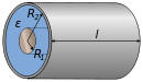
ε: Permittivity | |
| Pair of parallel wires[13] | 
| |
| Wire parallel to wall[13] | a: Wire radius d: Distance, d > a ℓ: Wire length | |
| Two parallel coplanar strips[14] |
d: Distance w1, w2: Strip width km: d/(2wm+d) k2: k1k2 | |
| Concentric spheres | 
ε: Permittivity | |
| Two spheres, equal radius[15][16] |
a: Radius d: Distance, d > 2a D = d/2a, D > 1 γ: Euler's constant | |
| Sphere in front of wall[15] | : Radius : Distance, | |
| Sphere | : Radius | |
| Circular disc[17] | : Radius | |
| Thin straight wire, finite length[18][19][20] |
: Wire radius : Length |


![{\displaystyle {\frac {2\pi \varepsilon \ell }{\Lambda }}\left\{1+{\frac {1}{\Lambda }}\left(1-\ln 2\right)+{\frac {1}{\Lambda ^{2}}}\left[1+\left(1-\ln 2\right)^{2}-{\frac {\pi ^{2}}{12}}\right]+O\left({\frac {1}{\Lambda ^{3}}}\right)\right\}}](https://wikimedia.org/api/rest_v1/media/math/render/svg/a19746fa861b22587cd9fbfcc0ed075187e6dc6a)


Energy storage[]
The energy (measured in joules) stored in a capacitor is equal to the work required to push the charges into the capacitor, i.e. to charge it. Consider a capacitor of capacitance C, holding a charge +q on one plate and −q on the other. Moving a small element of charge dq from one plate to the other against the potential difference V = q/C requires the work dW:

where W is the work measured in joules, q is the charge measured in coulombs and C is the capacitance, measured in farads.
The energy stored in a capacitor is found by integrating this equation. Starting with an uncharged capacitance (q = 0) and moving charge from one plate to the other until the plates have charge +Q and −Q requires the work W:

Nanoscale systems[]
The capacitance of nanoscale dielectric capacitors such as quantum dots may differ from conventional formulations of larger capacitors. In particular, the electrostatic potential difference experienced by electrons in conventional capacitors is spatially well-defined and fixed by the shape and size of metallic electrodes in addition to the statistically large number of electrons present in conventional capacitors. In nanoscale capacitors, however, the electrostatic potentials experienced by electrons are determined by the number and locations of all electrons that contribute to the electronic properties of the device. In such devices, the number of electrons may be very small, so the resulting spatial distribution of equipotential surfaces within the device are exceedingly complex.
Single-electron devices[]
The capacitance of a connected, or "closed", single-electron device is twice the capacitance of an unconnected, or "open", single-electron device.[21] This fact may be traced more fundamentally to the energy stored in the single-electron device whose "direct polarization" interaction energy may be equally divided into the interaction of the electron with the polarized charge on the device itself due to the presence of the electron and the amount of potential energy required to form the polarized charge on the device (the interaction of charges in the device's dielectric material with the potential due to the electron).[22]
Few-electron devices[]
The derivation of a "quantum capacitance" of a few-electron device involves the thermodynamic chemical potential of an N-particle system given by

whose energy terms may be obtained as solutions of the Schrödinger equation. The definition of capacitance,
- ,

with the potential difference

may be applied to the device with the addition or removal of individual electrons,
- and .


Then

is the "quantum capacitance" of the device.[23]
This expression of "quantum capacitance" may be written as

which differs from the conventional expression described in the introduction where , the stored electrostatic potential energy,


by a factor of 1/2 with .

However, within the framework of purely classical electrostatic interactions, the appearance of the factor of 1/2 is the result of integration in the conventional formulation,

which is appropriate since for systems involving either many electrons or metallic electrodes, but in few-electron systems, . The integral generally becomes a summation. One may trivially combine the expressions of capacitance and electrostatic interaction energy,


- and ,


respectively, to obtain,

which is similar to the quantum capacitance. A more rigorous derivation is reported in the literature.[24] In particular, to circumvent the mathematical challenges of the spatially complex equipotential surfaces within the device, an average electrostatic potential experienced by each electron is utilized in the derivation.
Apparent mathematical differences are understood more fundamentally as the potential energy, , of an isolated device (self-capacitance) is twice that stored in a "connected" device in the lower limit N=1. As N grows large, .[22] Thus, the general expression of capacitance is


- .

In nanoscale devices such as quantum dots, the "capacitor" is often an isolated, or partially isolated, component within the device. The primary differences between nanoscale capacitors and macroscopic (conventional) capacitors are the number of excess electrons (charge carriers, or electrons, that contribute to the device's electronic behavior) and the shape and size of metallic electrodes. In nanoscale devices, nanowires consisting of metal atoms typically do not exhibit the same conductive properties as their macroscopic, or bulk material, counterparts.
Capacitance in electronic and semiconductor devices[]
In electronic and semiconductor devices, transient or frequency-dependent current between terminals contains both conduction and displacement components. Conduction current is related to moving charge carriers (electrons, holes, ions, etc.), while displacement current is caused by a time-varying electric field. Carrier transport is affected by electric fields and by a number of physical phenomena - such as carrier drift and diffusion, trapping, injection, contact-related effects, impact ionization, etc. As a result, device admittance is frequency-dependent, and a simple electrostatic formula for capacitance is not applicable. A more general definition of capacitance, encompassing electrostatic formula, is:[25]


where is the device admittance, and is the angular frequency.


In general, capacitance is a function of frequency. At high frequencies, capacitance approaches a constant value, equal to "geometric" capacitance, determined by the terminals' geometry and dielectric content in the device. A paper by Steven Laux[25] presents a review of numerical techniques for capacitance calculation. In particular, capacitance can be calculated by a Fourier transform of a transient current in response to a step-like voltage excitation:
![{\displaystyle C(\omega )=1/(\Delta V)\int _{0}^{\infty }[i(t)-i(\infty )]cos(\omega t)dt.}](https://wikimedia.org/api/rest_v1/media/math/render/svg/2ae46997077cb3776ef3946fcc54a8bd0e56d58c)
Negative capacitance in semiconductor devices[]
Usually, capacitance in semiconductor devices is positive. However, in some devices and under certain conditions (temperature, applied voltages, frequency, etc.), capacitance can become negative. Non-monotonic behavior of the transient current in response to a step-like excitation has been proposed as the mechanism of negative capacitance.[26] Negative capacitance has been demonstrated and explored in many different types of semiconductor devices.[27]
Measuring capacitance[]
A capacitance meter is a piece of electronic test equipment used to measure capacitance, mainly of discrete capacitors. For most purposes and in most cases the capacitor must be disconnected from circuit.
Many DVMs (digital volt meters) have a capacitance-measuring function. These usually operate by charging and discharging the capacitor under test with a known current and measuring the rate of rise of the resulting voltage; the slower the rate of rise, the larger the capacitance. DVMs can usually measure capacitance from nanofarads to a few hundred microfarads, but wider ranges are not unusual. It is also possible to measure capacitance by passing a known high-frequency alternating current through the device under test and measuring the resulting voltage across it (does not work for polarised capacitors).

More sophisticated instruments use other techniques such as inserting the capacitor-under-test into a bridge circuit. By varying the values of the other legs in the bridge (so as to bring the bridge into balance), the value of the unknown capacitor is determined. This method of indirect use of measuring capacitance ensures greater precision. Through the use of Kelvin connections and other careful design techniques, these instruments can usually measure capacitors over a range from picofarads to farads.
See also[]
- Capacitive displacement sensor
- Capacity of a set
- Quantum capacitance
- Conductance
- Displacement current
- Ampère's circuital law
- Gauss law
- Hydraulic analogy
- Magnetocapacitance
- RKM code
- LCR meter
References[]
- ^ Harrington, Roger F. (2003). Introduction to Electromagnetic Engineering (1st ed.). Dover Publications. p. 43. ISBN 0-486-43241-6.
- ^ "Definition of 'farad'". Collins.
- ^ William D. Greason (1992). Electrostatic discharge in electronics. Research Studies Press. p. 48. ISBN 978-0-86380-136-5.
- ^ Lecture notes; University of New South Wales
- ^ Tipler, Paul; Mosca, Gene (2004). Physics for Scientists and Engineers (5th ed.). Macmillan. p. 752. ISBN 978-0-7167-0810-0.
- ^ Massarini, A.; Kazimierczuk, M.K. (1997). "Self capacitance of inductors". IEEE Transactions on Power Electronics. 12 (4): 671–676. Bibcode:1997ITPE...12..671M. CiteSeerX 10.1.1.205.7356. doi:10.1109/63.602562: example of the use of the term 'self capacitance'.CS1 maint: postscript (link)
- ^ Jackson, John David (1999). Classical Electrodynamic (3rd ed.). John Wiley & Sons. p. 43. ISBN 978-0-471-30932-1.
- ^ Maxwell, James (1873). "3". A treatise on electricity and magnetism. 1. Clarendon Press. p. 88ff.
- ^ "Capacitance : Charge as a Function of Voltage". Av8n.com. Retrieved 20 September 2010.
- ^ Smolić, Ivica; Klajn, Bruno (2021). "Capacitance matrix revisited". Progress In Electromagnetics Research B. 92: 1–18. doi:10.2528/PIERB21011501. Retrieved 4 May 2021.
- ^ "Capacitor MF-MMFD Conversion Chart". Just Radios.
- ^ Fundamentals of Electronics. Volume 1b — Basic Electricity — Alternating Current. Bureau of Naval Personnel. 1965. p. 197.
|volume=has extra text (help) - ^ Jump up to: a b Jackson, J. D. (1975). Classical Electrodynamics. Wiley. p. 80.
- ^ Binns; Lawrenson (1973). Analysis and computation of electric and magnetic field problems. Pergamon Press. ISBN 978-0-08-016638-4.
- ^ Jump up to: a b Maxwell, J. C. (1873). A Treatise on Electricity and Magnetism. Dover. p. 266ff. ISBN 978-0-486-60637-8.
- ^ Rawlins, A. D. (1985). "Note on the Capacitance of Two Closely Separated Spheres". IMA Journal of Applied Mathematics. 34 (1): 119–120. doi:10.1093/imamat/34.1.119.
- ^ Jackson, J. D. (1975). Classical Electrodynamics. Wiley. p. 128, problem 3.3.CS1 maint: postscript (link)
- ^ Maxwell, J. C. (1878). "On the electrical capacity of a long narrow cylinder and of a disk of sensible thickness". Proc. London Math. Soc. IX: 94–101. doi:10.1112/plms/s1-9.1.94.
- ^ Vainshtein, L. A. (1962). "Static boundary problems for a hollow cylinder of finite length. III Approximate formulas". Zh. Tekh. Fiz. 32: 1165–1173.
- ^ Jackson, J. D. (2000). "Charge density on thin straight wire, revisited". Am. J. Phys. 68 (9): 789–799. Bibcode:2000AmJPh..68..789J. doi:10.1119/1.1302908.
- ^ Raphael Tsu (2011). Superlattice to Nanoelectronics. Elsevier. pp. 312–315. ISBN 978-0-08-096813-1.
- ^ Jump up to: a b T. LaFave Jr. (2011). "Discrete charge dielectric model of electrostatic energy". J. Electrostatics. 69 (6): 414–418. arXiv:1203.3798. doi:10.1016/j.elstat.2011.06.006. S2CID 94822190.
- ^ G. J. Iafrate; K. Hess; J. B. Krieger; M. Macucci (1995). "Capacitive nature of atomic-sized structures". Phys. Rev. B. 52 (15): 10737–10739. Bibcode:1995PhRvB..5210737I. doi:10.1103/physrevb.52.10737. PMID 9980157.
- ^ T. LaFave Jr; R. Tsu (March–April 2008). "Capacitance: A property of nanoscale materials based on spatial symmetry of discrete electrons" (PDF). Microelectronics Journal. 39 (3–4): 617–623. doi:10.1016/j.mejo.2007.07.105. Archived from the original (PDF) on 22 February 2014. Retrieved 12 February 2014.
- ^ Jump up to: a b Laux, S.E. (October 1985). "Techniques for small-signal analysis of semiconductor devices". IEEE Transactions on Computer-Aided Design of Integrated Circuits and Systems. 4 (4): 472–481. doi:10.1109/TCAD.1985.1270145. S2CID 13058472.
- ^ Jonscher, A.K. (1986). "The physical origin of negative capacitance". J. Chem. Soc. Faraday Trans. II. 82: 75–81. doi:10.1039/F29868200075.
- ^ Ershov, M.; Liu, H.C.; Li, L.; Buchanan, M.; Wasilewski, Z.R.; Jonscher, A.K. (October 1998). "Negative capacitance effect in semiconductor devices". IEEE Trans. Electron Devices. 45 (10): 2196–2206. arXiv:cond-mat/9806145. Bibcode:1998ITED...45.2196E. doi:10.1109/16.725254.
Further reading[]
- Tipler, Paul (1998). Physics for Scientists and Engineers: Vol. 2: Electricity and Magnetism, Light (4th ed.). W. H. Freeman. ISBN 1-57259-492-6
- Serway, Raymond; Jewett, John (2003). Physics for Scientists and Engineers (6th ed.). Brooks Cole. ISBN 0-534-40842-7
- Saslow, Wayne M.(2002). Electricity, Magnetism, and Light. Thomson Learning. ISBN 0-12-619455-6. See Chapter 8, and especially pp. 255–259 for coefficients of potential.
| show Authority control |
|---|
- Capacitance
- Scalar physical quantities
- Electricity