Composite artifact colors


Composite artifact colors is a designation commonly used to address several graphic modes of some 1970s and 1980s home computers. With some machines, when connected to an NTSC TV or monitor over composite video outputs, the video signal encoding allowed for extra colors to be displayed, by manipulating the pixel position on screen, not being limited by each machine's hardware color palette (though, on modern TVs it might not work as well).
This mode was used mainly for games, since it limited the display's horizontal resolution more than normal. It was mostly used on the IBM PC (with CGA graphics),[1] TRS-80 Color Computer[2] and Apple II[3] computers, but was also utilized on Atari 8-bit most famously by the Ultima role-playing video games.[3]
The limitations of composite video regarding horizontal resolution were also exploited on other systems. Adjacent pixel values got averaged horizontally, producing solid colors or generating transparency effects.
On PAL displays (or NTSC 4.43 ones) this effect doesn't generate new colors, but rather a mix of adjacent horizontal pixel values. However, depending on the PAL system used, results will vary. If PAL M or PAL N are used color artifacts seen on NTSC might also be possible. If a higher resolution video connection is used, the graphics are displayed as dither patterns. Machines such as the ZX Spectrum or Mega Drive took advantage of this situation.
Technical details[]
In the NTSC color system as used in broadcasting, the color subcarrier frequency is exactly 227.5 times the line frequency, i.e., each line contains 227.5 color subcarrier cycles. This causes the apparent phase of the subcarrier to be reversed every line, which results in solid colors being displayed as a checkerboard-like pattern when viewed on a monochrome display that does not filter out the color information.[4]
Computers such as the Apple II[5] and the CGA[6][7] video card for the IBM PC, output a signal that is an approximation of the broadcast standard. In both the Apple II and the CGA, each line is elongated to full 228 cycles of the color subcarrier. This is within the tolerances of most displays, so the image is displayed clearly, but the pattern generated by solid colors becomes straight vertical stripes instead. Each horizontal position within any line has constant phase relationship to the color subcarrier under this system, so lighting up a pixel at each specific horizontal index always has the same effect on the color information as interpreted by the display.
It is also typical for these types of display adapters to have pixel clocks that are a multiple of the NTSC subcarrier frequency. Both the Apple II and the CGA use the pixel clock of 14.318 MHz, four times the color subcarrier. For a broadcast-quality signal, that would mean 910 pixel cycles per each line (as opposed to 858 as later standardized by the ITU-R Recommendation BT.601), with about 750 of them occupying the visible portion of the screen. With the stretched lines of these early computers, each line was actually 912 pixel cycles long, and only a portion of the visible area was used - 560 pixels in case of Apple II (although not individually addressable without an 80 column expansion card[8]), 640 in case of CGA. Each pixel could have one of the 4 predefined phase relationships to the color burst, so a "fake" subcarrier that will be interpreted as color by the display, can be constructed by outputting specific pixel patterns.[9]
In case of adapters that also have native color capabilities, such as the CGA, this technique can be further expanded by forming patterns out of the built-in colors - this way, the "real" subcarrier generated by the hardware will interfere with the "fake" one residing within the pixel patterns, causing the display to interpret the result as new, unique colors.[10]
In the PAL system, the phase of the subcarrier is interpreted differently from line to line, and the phase of the color burst is strictly required to change on alternate lines. This makes the tricks described above infeasible. SECAM uses frequency modulation, so generating artifact colors would require timing far more precise than synchronizing the pixel clock to the subcarrier frequency of either NTSC or PAL. For these reasons, artifact colors were generally only used with the NTSC color system. They are theoretically possible in any of them, due to the fact that in every analog television system, color information resides within the same bandwidth as luminance information.
Machines[]
PC compatibles with CGA graphic cards[]
When using IBM's Color Graphics Adapter (CGA) with NTSC TV-out the separation between luminance and chrominance is imperfect, yielding cross-color artifacts. This is especially a problem with 80-column text.
It is for this reason that each of the text and graphics modes described above exists twice: Once as the normal "color" version and once as a "monochrome" version. The "monochrome" version of each mode turns off the NTSC color decoding in the viewing monitor completely, resulting in a black-and-white picture, but also no color bleeding, hence, a sharper picture. On RGBI monitors, the two versions of each mode are identical, with the exception of the 320×200 graphics mode, where the "monochrome" version produces the third palette.
However, programmers learned that this flaw could be turned into an asset, as distinct patterns of high-resolution dots would turn into consistent areas of solid colors, thus allowing the display of completely new colors. Since these new colors are the result of cross-color artifacting, they are often called "artifact colors". Both the standard 320×200 four-color and the 640×200 color-on-black graphics modes could be used with this technique.
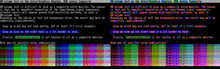
Early efforts resulted on a usable resolution of 160×200 with 16 colors.[11] Actual colors depend on the base palette and resolution used, as shown on the gallery below:
320×200 palette 0

320×200 palette 1

640×200
Later demonstrations by enthusiasts have increased the maximum number of colors the CGA can display at the same time to 1024. This technique involves a text mode tweak which quadruples the number of text rows. Certain ASCII characters such as U and ‼ are then used to produce the necessary patterns, which result in non-dithered images with an effective resolution of 80×100 on a composite monitor.[12]
Software support[]
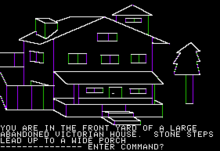
Many of the more high-profile game titles offers graphics optimized for composite color monitors.[13] Ultima II, the first game in the game series to be ported to IBM PC, uses CGA composite graphics. King's Quest I was also innovative in its use of 16-color graphics. Other titles include Microsoft Decathlon, King's Quest II and King's Quest III.
TRS-80 Color Computer[]
The TRS-80 Color Computer 256×192 two color graphics mode uses four colors due to a quirk in the NTSC television system. It is not possible to reliably display 256 dots across the screen due to the limitations of the NTSC signal and the phase relationship between the VDG clock and colorburst frequency. In the first colorset, where green and black dots are available, alternating columns of green and black are not distinct and appear as a muddy green color. However, when one switches to the white and black colorset, instead of a muddy gray as expected, the result is either orange or blue. Reversing the order of the alternating dots will give the opposite color. In effect this mode becomes a 128×192 4 color graphics mode where black, orange, blue, and white are available (the Apple II created color graphics by exploiting a similar effect). Most CoCo games used this mode as the colors available are more useful than the ones provided in the hardware 4 color modes. The VDG internally can power up on either the rising or falling edge of the clock, so the bit patterns that represent orange and blue are not predictable. Most CoCo games start with a title screen and asks the user to press the reset button until the colors are correct. The CoCo 3 fixes the clock-edge problem so it is always the same; a user holds the F1 key during reset to choose the other color set. On a CoCo 3 with an analog RGB monitor, the black and white dot patterns do not artifact; to see them one uses a TV or composite monitor, or patch the games to use the hardware 128×192 four color mode in which the GIME chip allows the color choices to be mapped.
Readers of The Rainbow or Hot CoCo magazine learned that they can use some POKE commands to switch the 6847 VDG into one of the artifact modes, while Extended Color Basic continues to operate as though it were still displaying one of the 128x192 four-color modes. Thus, the entire set of Extended Color Basic graphics commands can be used with the artifact colors. Some users developed a set of 16 artifact colors[how?] using a 4×2 pixel matrix. Use of POKE commands also make these colors available to the graphics commands, although the colors have to be drawn one horizontal line at a time. Some interesting artworks were produced from these effects, especially since the CoCo Max art package provides them in its palette of colors.
The resulting 16 color palette is:
- black
- dark cyan
- brick red
- light violet
- dark blue
- azure
- olive green
- brown
- purple
- light blue
- orange
- yellow
- light gray
- blue-white
- pink-white
- white
Apple II[]
Color graphics on the Apple II series uses a quirk of the NTSC television signal standard, which made color display relatively easy and inexpensive to implement.
The Apple II display provides two pixels per NTSC subcarrier cycle. When the color burst reference signal is on and the computer attached to a color display, it can display green by showing one alternating pattern of pixels, magenta with an opposite pattern of alternating pixels, and white by placing two pixels next to each other. Later, blue and orange became available by tweaking the offset of the pixels by half a pixel-width in relation to the color-burst signal. The high-resolution display offers more colors simply by compressing more, narrower pixels into each subcarrier cycle.
The coarse, low-resolution graphics display mode works differently, as it can output a pattern of dots per pixel to offer more color options. These patterns are stored in the character generator ROM and replaces the text character bit patterns when the computer is switched to low-res graphics mode. The text mode and low-res graphics mode uses the same memory region and the same circuitry is used for both.
Atari 8-bit[]
Graphics 8 mode on early Atari 8-bit computers that used the Color Television Interface Adaptor (CTIA) chip displayed black or white images at a resolution of 320×192.
Programmers quickly discovered that the odd or even patterns of adjacent white pixels in this mode would generate one of two additional colours and software such as On-Line Systems' The Wizard and the Princess used this side-effect to display up to four colors at maximum resolution. This technique and its technical underpinnings were documented in Appendix D of De Re Atari.
When Atari began shipping computers with the improved Graphic Television Interface Adaptor (GTIA), users found that such programs displayed incorrect colors and required an updated version of the software.[14]
In fact, artifact colors were inconsistent across the entire Atari 8-bit product line complicating playfield design but only affected a handful of titles that used this graphics mode. These color differences can be simulated within Altirra-based emulators.
All models with RF or composite output connected to televisions exhibited this effect while those such as the original Atari 800 or later XE series with built-in chroma/luma support additionally displayed images without artifacts when connected to a computer monitor with chroma/luma inputs such as the Commodore 1701) .
For some undocumented reason known only to Atari, they did not enable the chroma pin on the monitor jack of the 800XL although several modifications have been published to incorporate this support.
Other machines[]
Many first generation MSX computer games use Composite Artifact Colors (horizontal blurring) to generate a palette of 125 simultaneous colors. Companies like Konami, Hal Laboratory or Ponyca used this technique regularly. SONY's Graphic Master design program allowed these 125 colors to be used in user-created drawings.
Home computers like the Atari ST or the Commodore Amiga also have graphics prepared with dithering techniques to take advantage of composite TV connections. Regarding the Amiga, the special Hold-And-Modify is particularly suited for displaying "high color" TV-like images, taking full advantage of horizontal blurring.
The Mega Drive takes advantage of horizontal blurring of checkerboard dither patterns to simulate transparency effects on many games.
PAL system[]
Using a composite connection with the PAL TV system will not generate new colors, but instead a horizontal blurring effect. Given the different bandwidths of the PAL broadcast systems (PAL-M, PAL-N, PAL-B, etc..), the actual effect intensity will vary. This effect will be more pronounced if higher display resolutions are used, and as such was exploited by game artists on some machines using dithering patterns.
Apple II[]
The Apple II could be modified to output a 50 Hz signal for use in PAL and SECAM regions. However, when connected directly to a display, it would result in a black and white picture. "Eurocolor" expansion cards were available that would essentially decode NTSC artifacts and re-encode them as PAL or SECAM.[15]
TRS-80 Color Computer[]
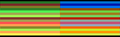
TRS-80 Color Computer users in PAL countries would only see green and purple stripes instead of solid red and blue colors.
References[]
- ^ "Exodus Project / Wiki / CGA Composite". Sourceforge.net. Retrieved 7 August 2016.
- ^ "256 color mode (composite mode artifacting) - The TRS-80/Tandy Color Computer COCO SuperSite!". Coco3.com. Retrieved 7 August 2016.
- ^ a b "Nerdly Pleasures: The Overlooked Artifact Color Capabilities of non-Apple II Computers". Nerdlypleasures.blogspot.pt. 24 September 2013. Retrieved 7 August 2016.
- ^ Pemberton, Alan. "World Analogue Television Standards and Waveforms - Colour Standards - Choice of Subcarrier Frequency (fSC)". Pember's Ponderings. Archived from the original on 16 July 2016.
- ^ Gayler, Winston D. (1983), The Apple II Circuit Description (PDF), Indianapolis, IN 46268: Howard W. Sams & Co., Inc., p. 30, retrieved 3 May 2021CS1 maint: location (link)
- ^ IBM, IBM Color/Graphics Monitor Adapter (Personal Computer Hardware Reference Library) (PDF), p. 17, retrieved 3 May 2021
- ^ Motorola, MC6845 CRT Controller (PDF), p. 4-465, retrieved 3 May 2021
- ^ Lukazi (25 March 2017). "Double High Resolution Graphics (DHGR) - Pushing Limits". Apple II Projects. Archived from the original on 26 January 2021.
- ^ Munafo, Robert P. (26 March 2020). "Apple ][ Colors". MROB. Archived from the original on 9 September 2020.
- ^ VileR (15 April 2015). "CGA in 1024 Colors - a New Mode: the Illustrated Guide". int10h.org. Archived from the original on 24 March 2021.
- ^ "Colour Graphics Adapter Notes". Seasip.info. 6 December 2006. Retrieved 7 August 2016.
- ^ "CGA in 1024 Colors - a New Mode: the Illustrated Guide". A blog entry by the creators of the demo "8088 MPH" explaining this technique.
- ^ "Nerdly Pleasures: IBM PC Color Composite Graphics". Nerdlypleasures.blogspot.pt. 2 November 2013. Retrieved 7 August 2016.
- ^ Small, David; Small, Sandy; Blank, George, eds. (1983). "The Wizard, the Princess, and the Atari". The Creative Atari. Creative Computing Press. ISBN 0916688348.
- ^ Espinosa, Christopher (1979), Apple II Reference Manual, Cupertino, CA 95014: Apple Computer, Inc., p. 10, retrieved 3 May 2021CS1 maint: location (link)
- Computer graphic artifacts
- Computer graphic techniques
- Computer display standards
- Composite video formats