Differential (mechanical device)
This article needs additional citations for verification. (July 2015) |

A differential is a gear train with three shafts that has the property that the rotational speed of one shaft is the average of the speeds of the others, or a fixed multiple of that average.
Functional description[]


The following description of a differential applies to a traditional rear-wheel-drive car or truck with an open or limited slip differential combined with a reduction gearset using bevel gears (these are not strictly necessary – see spur-gear differential):
Thus, for example, if the car is making a turn to the right, the main ring gear may make 10 full rotations. During that time, the left wheel will make more rotations because it has farther to travel, and the right wheel will make fewer rotations as it has less distance to travel. The sun gears (which drive the axle half-shafts) will rotate at different speeds relative to the ring gear (one faster, one slower) by, say, 2 full turns each (4 full turns relative to each other), resulting in the left wheel making 12 rotations, and the right wheel making 8 rotations.
The rotation of the ring gear is always the average of the rotations of the side sun gears. This is why if the driven roadwheels are lifted clear of the ground with the engine off, and the drive shaft is held (say, leaving the transmission in gear preventing the ring gear from turning inside the differential), manually rotating one driven roadwheel causes the opposite roadwheel to rotate in the opposite direction by the same amount.
When the vehicle is traveling in a straight line there will be no differential movement of the planetary system of gears other than the minute movements necessary to compensate for slight differences in wheel diameter, undulations in the road which make for a longer or shorter wheel path, etc.
Applications[]


In automobiles and other wheeled vehicles, the differential allows the outer drive wheel to rotate faster than the inner drive wheel during a turn. This is necessary when the vehicle turns, making the wheel that is traveling around the outside of the turning curve roll farther and faster than the other. The average of the rotational speed of the two driving wheels equals the input rotational speed of the drive shaft. An increase in the speed of one wheel is balanced by a decrease in the speed of the other.
When used in this way, a differential couples the longitudinal input propeller shaft to the pinion, which in turn drives the transverse ring gear of the differential. This also usually works as reduction gearing. On rear wheel drive vehicles the differential may connect to half-shafts inside an axle housing, or drive shafts that connect to the rear driving wheels. Front wheel drive vehicles tend to have the engine crankshaft and the gearbox shafts transverse, and with the pinion on the end of the counter-shaft of the gearbox and the differential enclosed in the same housing as the gearbox. There are individual drive-shafts to each wheel. A differential consists of one input (the drive shaft) and two outputs, which are connected to the two drive wheels; however the rotations of the drive wheels are coupled to each other by their connection to the roadway. Under normal conditions, with small tyre slip, the ratio of the speeds of the two driving wheels is defined by the ratio of the radii of the paths around which the two wheels are rolling, which in turn is determined by the track-width of the vehicle (the distance between the driving wheels) and the radius of the turn.
Non-automotive uses of differentials include performing analog arithmetic. Two of the differential's three shafts are made to rotate through angles that represent (are proportional to) two numbers, and the angle of the third shaft's rotation represents the sum or difference of the two input numbers. The earliest known use of a differential gear is in the Antikythera mechanism, circa 80 BCE, which used a differential gear to control a small sphere representing the moon from the difference between the sun and moon position pointers. The ball was painted black and white in hemispheres, and graphically showed the phase of the moon at a particular point in time.[1] An equation clock that used a differential for addition was made in 1720. In the 20th Century, large assemblies of many differentials were used as analog computers, calculating, for example, the direction in which a gun should be aimed.[2]
History[]
There are many claims to the invention of the differential gear, but it is possible that it was known, at least in some places, in ancient times. Confirmed historical milestones of the differential include:
- 100 BCE–70 BCE: The Antikythera mechanism has been dated to this period. It was discovered in 1902 on a shipwreck by sponge divers, and modern research suggests that it used a differential gear to determine the angle between the ecliptic positions of the Sun and Moon, and thus the phase of the Moon.[1][3]
- c. 250 CE: Chinese engineer Ma Jun creates the first well-documented south-pointing chariot, a precursor to the compass that uses differential gears to discern direction rather than a magnet.
- 1720: Joseph Williamson uses a differential gear in a clock.
- 1810: Rudolph Ackermann of Germany invents a four-wheel steering system for carriages, which some later writers mistakenly report as a differential.
- 1827: modern automotive differential patented by watchmaker Onésiphore Pecqueur (1792–1852) of the Conservatoire National des Arts et Métiers in France for use on a steam wagon.[4][5]
- 1832: Richard Roberts of England patents "gear of compensation", a differential for road locomotives.
- 1874: Aveling and Porter of Rochester, Kent list a crane locomotive in their catalogue fitted with their patent differential gear on the rear axle.[6]
- 1876: James Starley of Coventry invents chain-drive differential for use on bicycles; invention later used on automobiles by Karl Benz.
- 1897: first use of differential on an Australian steam car by David Shearer.
- 1958: patents the Torsen dual-drive differential, a type of limited-slip differential that relies solely on the action of gearing, instead of a combination of clutches and gears.
Epicyclic differential[]
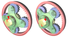
An epicyclic differential can use epicyclic gearing to split and apportion torque asymmetrically between the front and rear axles. An epicyclic differential is at the heart of the Toyota Prius automotive drive train, where it interconnects the engine, motor-generators, and the drive wheels (which have a second differential for splitting torque as usual). It has the advantage of being relatively compact along the length of its axis (that is, the sun gear shaft).
Epicyclic gears are also called planetary gears because the axes of the planet gears revolve around the common axis of the sun and ring gears that they mesh with and roll between. In the image, the yellow shaft carries the sun gear which is almost hidden. The blue gears are called planet gears and the pink gear is the ring gear or annulus.
Ring gears are also used in starter motors.
Spur-gear differential[]
A spur-gear differential has two equal-sized spur gears, one for each half-shaft, with a space between them. Instead of the Bevel gear, also known as a miter gear, assembly (the "spider") at the centre of the differential, there is a rotating carrier on the same axis as the two shafts. Torque from a prime mover or transmission, such as the drive shaft of a car, rotates this carrier.
Mounted in this carrier are one or more pairs of identical gears, generally longer than their diameters, and typically smaller than the spur gears on the individual half-shafts. Each pinion pair rotates freely on pins supported by the carrier. Furthermore, the pinion pairs are displaced axially, such that they mesh only for the part of their length between the two spur gears, and rotate in opposite directions. The remaining length of a given pinion meshes with the nearer spur gear on its axle. Therefore, each pinion couples that spur gear to the other pinion, and in turn, the other spur gear, so that when the drive shaft rotates the carrier, its relationship to the gears for the individual wheel axles is the same as that in a bevel-gear differential.
A spur gear differential is constructed from two identical coaxial epicyclic gear trains assembled with a single carrier such that their planet gears are engaged. This forms a planetary gear train with a fixed carrier train ratio R = -1.
In this case, the fundamental formula for the planetary gear train yields,


Thus, the angular velocity of the carrier of a spur gear differential is the average of the angular velocities of the sun and annular gears.[7][page needed]
Non-automotive applications[]

Chinese south-pointing chariots may also have been very early applications of differentials. The chariot had a pointer which constantly pointed to the south, no matter how the chariot turned as it travelled. It could therefore be used as a type of compass. It is widely thought that a differential mechanism responded to any difference between the speeds of rotation of the two wheels of the chariot, and turned the pointer appropriately. However, the mechanism was not precise enough, and, after a few miles of travel, the dial could have very well been pointing in the completely opposite direction.
The earliest definitely verified use of a differential was in a clock made by Joseph Williamson in 1720. It employed a differential to add the equation of time to local mean time, as determined by the clock mechanism, to produce solar time, which would have been the same as the reading of a sundial. During the 18th Century, sundials were considered to show the "correct" time, so an ordinary clock would frequently have to be readjusted, even if it worked perfectly, because of seasonal variations in the equation of time. Williamson's and other equation clocks showed sundial time without needing readjustment. Nowadays, we consider clocks to be "correct" and sundials usually incorrect, so many sundials carry instructions about how to use their readings to obtain clock time.
In the first half of the twentieth century, mechanical analog computers, called differential analyzers, were constructed that used differential gear trains to perform addition and subtraction. The U.S. Navy Mk.1 gun fire control computer used about 160 differentials of the bevel-gear type.
A differential gear train can be used to allow a difference between two input axles. Mills often used such gears to apply torque in the required axis. Differentials are also used in this way in watchmaking to link two separate regulating systems with the aim of averaging out errors. Greubel Forsey use a differential to link two double tourbillon systems in their Quadruple Differential Tourbillon.
Application to vehicles[]

A vehicle with two drive wheels has the problem that when it turns a corner the drive wheels must rotate at different speeds to maintain traction. The automotive differential is designed to drive a pair of wheels while allowing them to rotate at different speeds. In vehicles without a differential, such as karts, both driving wheels are forced to rotate at the same speed, usually on a common axle driven by a simple chain-drive mechanism.
When cornering, the inner wheel travels a shorter distance than the outer wheel, so without a differential either the inner wheel rotates too quickly or the outer wheel rotates too slowly, which results in difficult and unpredictable handling, damage to tires and roads, and strain on (or possible failure of) the drivetrain.
In rear-wheel drive automobiles the central drive shaft (or prop shaft) engages the differential through a hypoid gear (ring and pinion). The ring gear is mounted on the carrier of the planetary chain that forms the differential. This hypoid gear is a bevel gear that changes the direction of the drive rotation.

Loss of traction[]
One undesirable side effect of an open differential is that it can limit traction under less than ideal conditions. The amount of traction required to propel the vehicle at any given moment depends on the load at that instant—how heavy the vehicle is, how much drag and friction there is, the gradient of the road, the vehicle's momentum, and so on.
The torque applied to each driving wheel is the result of the engine, transmission and drive axle applying a twisting force against the resistance of the traction at that roadwheel. In lower gears, and thus at lower speeds, and unless the load is exceptionally high, the drivetrain can supply as much torque as necessary, so the limiting factor becomes the traction under each wheel. It is therefore convenient to define traction as the amount of force that can be transmitted between the tire and the road surface before the wheel starts to slip. If the torque applied to one of the drive wheels exceeds the threshold of traction, then that wheel will spin, and thus provide torque only at the other driven wheel equal to the sliding friction at the slipping wheel. The reduced net traction may still be enough to propel the vehicle slowly.
An open (non-locking or otherwise traction-aided) differential always supplies close to equal torque to each side. To illustrate how this can limit torque applied to the driving wheels, imagine a simple rear-wheel drive vehicle, with one rear roadwheel on asphalt with good grip, and the other on a patch of slippery ice. It takes very little torque to spin the side on slippery ice, and because a differential splits torque equally to each side, the torque that is applied to the side that is on asphalt is limited to this amount.[8][9]
Based on the load, gradient, etc., the vehicle requires a certain amount of torque applied to the drive wheels to move forward. Since an open differential limits total torque applied to both drive wheels to the amount used by the lower traction wheel multiplied by two, when one wheel is on a slippery surface, the total torque applied to the driving wheels may be lower than the minimum torque required for vehicle propulsion.[10]
A proposed alternate way to distribute power to the wheels, is to use the concept of a gearless differential, about which a review has been reported by Provatidis,[11] but the various configurations seem to correspond either to the "sliding pins and cams" type, such as the ZF B-70 available on early Volkswagens, or are a variation of the ball differential.
Many newer vehicles feature traction control, which partially mitigates the poor traction characteristics of an open differential by using the anti-lock braking system to limit or stop the slippage of the low traction wheel, increasing the torque that can be applied to the opposite wheel. While not as effective as a traction-aided differential, it is better than a simple mechanical open differential with no traction assistance.
Active differentials[]
Fully integrated active differentials are used on the Ferrari F430, Mitsubishi Lancer Evolution, Lexus RC F and GS F, and on the rear wheels in the Acura RL. A version manufactured by ZF is also being offered on the B8 chassis Audi S4 and Audi A4.[12] The Volkswagen Golf GTI Mk7 in Performance trim also has an electronically controlled front-axle transverse differential lock, also known as VAQ.[13] The 2016 Ford Focus RS has a different type of differential setup. This essentially gives each wheel its own differential. This allows Torque vectoring and can send power to any wheel that needs it.[14]
Enthusiast interest[]
Drifting is a popular motorsport style that has its origins in the mountains of Japan. This style of driving is known for sliding a car through a corner without leaving the road surface. To easily get the car into a slide the driver can use a Limited-slip differential or a welded differential. A limited slip differential makes the wheels of the vehicle turn at the same speed. Since the inside wheel of the car is going a shorter distance than the outside wheel, this causes slippage. This slippage is what makes it easier to slide the car around a turn.[15]
See also[]
- Ball differential
- Equation clock
- Hermann Aron § Electricity meters
- Limited slip differential
- Locking differential
- Torque vectoring
- Whippletree
References[]
- ^ a b Wright, M. T. (2007). "The Antikythera Mechanism reconsidered" (PDF). Interdisciplinary Science Reviews. 32 (1): 27–43. doi:10.1179/030801807X163670. S2CID 54663891. Retrieved 20 May 2014.
- ^ Basic Mechanisms in Fire Control Computers, Part 1, Shafts Gears Cams and Differentials, posted as 'U.S. Navy Vintage Fire Control Computers' (Training Film). U.S. Navy. 1953. Event occurs at 37 seconds. MN-6783a. Archived from the original on 18 November 2021. Retrieved 20 September 2021.
- ^ Presentation given to the NHRF in Athens, 6 March 2007 – M. T. Wright
- ^ Britannica Online
- ^ "History of the Automobile". General Motors Canada. Retrieved 9 January 2011.
- ^ Preston, J.M. (1987), Aveling & Porter, Ltd. Rochester., North Kent Books, pp. 13–14, ISBN 0-948305-03-7 includes sectional drawing.
- ^ Uicker, J. J.; Pennock, G. R.; Shigle, J. E. (2003). Theory of Machines and Mechanisms (3rd ed.). New York: Oxford University Press. ISBN 9780195155983.
- ^ Bonnick, Allan (2001). Automotive Computer Controlled Systems. p. 22. ISBN 9780750650892.
- ^ Bonnick, Allan (2008). Automotive Science and Mathematics. p. 123. ISBN 9780750685221.
- ^ Chocholek, S. E. (1988). "The Development of a Differential for the Improvement of Traction Control".
- ^ Provatidis, Christopher G. (2003). "A Critical Presentation of Tsiriggakis' Gearless Differential". Mobility & Vehicles Mechanics. 29 (4): 25–46.
- ^ "ZF Press release". ZF.com. Retrieved 9 January 2011.
- ^ "Golf VII GTI". PistonHeads.com. Retrieved 24 June 2013.
- ^ "The 2016 Ford Focus RS Gets an Advanced Torque-Vectoring AWD System". Automobile. 4 November 2015. Retrieved 21 September 2020.
- ^ Skwarczek, Matthew (29 March 2020). "What Makes a Limited-Slip Differential Desirable?". MotorBiscuit. Retrieved 21 September 2020.
External links[]
| Wikimedia Commons has media related to Automobile differentials. |
- A video of a 3D model of an open differential
- Popular Science, May 1946, How Your Car Turns Corners, a large article with numerous illustrations on how differentials work
- Auto parts
- Automotive transmission technologies
- Mechanisms (engineering)
- Vehicle technology
- Gears