Fatigue testing
Fatigue testing is a specialised form of mechanical testing that is performed by applying cyclic loading to a coupon or structure. These tests are used either to generate fatigue life and crack growth data, identify critical locations or demonstrate the safety of a structure that may be susceptible to fatigue. Fatigue tests are used on a range components from coupons through to full size test articles such as automobiles and aircraft.
Fatigue tests on coupons are typically conducted using servo hydraulic test machines which are capable of applying large variable amplitude cyclic loads.[2] Constant amplitude testing can also be applied by simpler oscillating machines. The fatigue life of a coupon is the number of cycles it takes to break the coupon. This data can be used for creating stress-life or strain-life curves. The rate of crack growth in a coupon can also be measured, either during the test or afterward using fractography. Testing of coupons can also be carried out inside environmental chambers where the temperature, humidity and environment that may affect the rate of crack growth can be controlled.
Because of the size and unique shape of full size test articles, special test rigs are built to apply loads through a series of hydraulic or electric actuators. Actuators aim to reproduce the significant loads experienced by a structure, which in the case of aircraft, may consist of manoeuvre, gust, buffet and ground-air-ground (GAG) loading. A representative sample or block of loading is applied repeatedly until the safe life of the structure has been demonstrated or failures occur which need to be repaired. Instrumentation such as load cells, strain gauges and displacement gauges are installed on the structure to ensure the correct loading has been applied. Periodic inspections of the structure around critical stress concentrations such as holes and fittings are made to determine the time detectable cracks were found and to ensure any cracking that does occur, does not affect other areas of the test article. Because not all loads can be applied, any unbalanced structural loads are typically reacted out to the test floor through non-critical structure such as the undercarriage.
Airworthiness standards generally require a fatigue test to be carried out for large aircraft prior to certification to determine their safe life.[3] Small aircraft may demonstrate safety through calculations, although typically larger scatter or safety factors are used because of the additional uncertainty involved.
Coupon tests[]

Fatigue tests are used to obtain material data such as the rate of growth of a fatigue crack that can be used with crack growth equations to predict the fatigue life. These tests usually determine the rate of crack growth per cycle versus the stress intensity factor range , where the minimum stress intensity factor corresponds to the minimum load for and is taken to be zero for , and is the stress ratio . Standardised tests have been developed to ensure repeatability and to allow the stress intensity factor to be easily determined but other shapes can be used providing the coupon is large enough to be mostly elastic.[4]


Coupon shape[]
A variety of coupons can be used but some of the common ones are:
- compact tension coupon (CT). The compact specimen uses the least amount of material for a specimen that is used to measure crack growth.[4] Compact tension specimens typically use pins that are slightly smaller than the holes in the coupon to apply the loads. This method however prevents the accurate application of loads near zero and the coupon is therefore not recommended when negative loads need to be applied.[4]
- Centre Cracked Tension panel (CCT). The centre cracked tension or middle tension specimen is made from a flat sheet or bar containing two holes for attaching to grips .
- Single Edge Notch Tension coupon (SENT).[5] The single edge coupon is an elongated version of the compact tension coupon.
| Formulae for stress intensity range |
|---|
Compact tension specimen[]The recommended thickness is .[4] The stress intensity range for compact coupons can be calculated from the applied load for a specimen of width using[4] where and is the crack length and is the distance between the applied load and the backface of the coupon. This equation is valid for . Centre cracked tension specimen[]This coupon has a central crack of length . The following empirical criterion is used to ensure the specimen is large enough to ensure assumption of linear elastic fracture mechanics are met[4] where is the 0.2% offset yield stress and is the coupon thickness. The stress intensity range for the coupon can be calculated from[4] Single edge crack specimen[]This coupon with a side crack of length . The minimum size of the specimen is given by[4] The stress intensity range for this coupon is[4] where is and is and . |


Instrumentation[]
The following instrumentation is commonly used for monitoring coupon tests:
- Strain gauges are used to monitor the applied loading or stress fields around the crack tip. They may be placed beneath the path of the crack or on the back face of a compact tension coupon.[6]
- An extensometer or displacement gauge can be used to measure the crack tip opening displacement at the mouth of a crack. This value can be used to determine the stress intensity factor which will change with the length of the crack. Displacement gauges can also be used to measure the compliance of a coupon and the position during the loading cycle when contact between the opposite crack faces occurs in order to measure crack closure.
- Applied test loads are usually monitored on the test machine with a load cell.
- A travelling optical microscope can be use for measurement of the position of the crack tip.
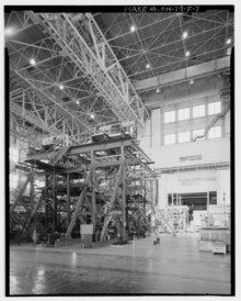
Full scale fatigue tests[]

Full-scale tests may be used to:
- Validate the proposed aircraft maintenance schedule.
- Demonstrate the safety of a structure that may be susceptible to widespread fatigue damage.
- Generate fatigue data
- Validate expectations for crack initiation and growth pattern.
- Identify critical locations
- Validate software used to design and manufacture the aircraft.
Fatigue tests can also be used to determine the extent that widespread fatigue damage may be a problem.
Test article[]
Certification requires knowing and accounting for the complete load history that has been experienced by a test article. Using test articles that have previously been used for static proof testing have caused problems where overloads have been applied and that can retard the rate of fatigue crack growth.
The test loads are typically recorded using a data acquisition system acquiring data from possibly thousands of inputs from instrumentation installed on the test article, including: strain gages, pressure gauges, load cells, LVDTs, etc.
Fatigue cracks typically initiate from high stress regions such as stress concentrations or material and manufacturing defects. It is important that the test article is representative of all of these features.
Cracks may initiate from the following sources:
- Fretting, typically from high cycle count dynamic loads.
- Mis-drilled holes or incorrectly sized holes for interference fit fasteners.[7]
- Material treatment and defects such as broken inclusions.[8]
- Stress concentrations such as holes and fillets.
- Scratches, impact damage.
Loading sequence[]
A representative block of loading is applied repeatedly until the safe life of the structure has been demonstrated or failures occur which need to be repaired. The size of the sequence is chosen so that the maximum loads which may cause retardation effects are applied sufficiently often, typically at least ten times throughout the test, so that there are no sequence effects.[9]
The loading sequence is generally filtered to eliminate applying small non-fatigue damaging cycles that would take too long to apply. Two types of filtering are typically used:
- deadband filtering eliminates small cycles that completely fall within a certain range such as +/-3g.
- rise-fall filtering eliminates small cycles that are less than a certain range such as 1g.
The testing rate of large structures is typically limited to a few Hz and needs to avoid the resonance frequency of the structure.[10]
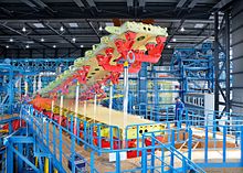
Test rig[]
All components that are not part of the test article or instrumentation are termed the test rig. The following components are typically found in full scale fatigue tests:
- Whiffletrees. In order to apply the correct loads to various parts of the structure, a mechanism known as a whiffletree is used to distribute the loads from a loading actuator to the test article. Loads applied to a central point are distributed through a series of pin jointed connected beams to produce known loads at the end connections. Each end connection is typically attached to a pad which is bonded onto the structure such as an aircraft wing. Hundreds of pads are usually applied to reproduce the aerodynamic and inertial loads seen on wing. Because the whiffletree consists of tension linkages, they are unable to apply compressive loads and therefore, independent whiffletrees are typically used on the upper and lower sides of wing fatigue tests.
- Hydraulic, electromagnetic or pneumatic actuators are used to apply loads to the structure, either directly or through the use of a whiffletree to distribute the loads. A load cell is placed inline with the actuator and is used by the load controller to control the loads into the actuator. When many actuators are used on a flexible test structure, there may be cross-interaction between the different actuators. The load controller must ensure that spurious loading cycles are not applied to the structure as a result of this interaction.
- Reaction restraints. Many of the loads such as aerodynamic and internal forces are re-acted by internal forces which are not present during a fatigue test. Hence, the loads are reacted out of the structure at non-critical points such as the undercarriage or through restraints on the fuselage.
- Linear variable differential transformer can be used to measure the displacement of critical locations on the structure. Limits on these displacements can be used to signal when a structure has failed and to automatically shut down the test.
- Non-representative structure. Some test structure may be expensive or unavailable and are typically replaced on the test structure with an equivalent structure. Structure that is close to actuator attachment points may see an unrealistic load that makes these areas non-representative.
Instrumentation[]
The following instrumentation is typically used on a fatigue test:
- strain gauges
- accelerometers
- displacement gauges
- load cells
- crack sensor
- structural health monitoring sensors
It is important to install any strain gauges on the test article that are also used for monitoring fleet aircraft. This allows the same damage calculations to be performed on the test article that are used to track the fatigue life of fleet aircraft. This is the primary way of ensuring fleet aircraft do not exceed the safe-life determined from the fatigue test.
Inspections[]
Inspections form a component of a fatigue test. It is important to know when a detectable crack occurs in order to determine the certified life of each component in addition to minimising the damage to surrounding structure and to develop repairs that have minimal impact on the certification of the adjacent structure. Non-destructive inspections may be carried out during testing and destructive tests may be used at the end of testing to ensure the structure retains its load carrying capacity.
Certification[]
Test interpretation and certification involves using the results from the fatigue test to justify the safe life and operation of an item.[11] The purpose of certification is to ensure the probability of failure in service is acceptably small. The following factors may need to be considered:
- number of tests
- symmetry of the test structure and the applied loading
- installation and certification of repairs
- scatter factors
- material and manufacturing process variability
- environment
- criticality
Airworthy standards typically require that an aircraft remains safe even with the structure in a degraded state due to the presence of fatigue cracking.[12]
Notable fatigue tests[]
- Cold proof loading tests of the F-111. These tests involved applying static limit loads to aircraft which had been chilled to reduce the critical fracture size. Passing the test meant that there were no large fatigue cracks present. When cracks were present, the wings failed catastrophically.[8]
- The International Follow-On Structural Fatigue Test Program (IFOSTP) was a joint venture between Australia, Canada and the U.S. to fatigue test the F/A-18 Hornet. The Australian test involved the use of electrodynamic shakers and pneumatic airbags to simulate high angle of attack buffet loads over the empennage.[13][14]
- de Havilland Comet suffered a series of catastrophic failures that ultimately proved to be fatigue despite being fatigue tested.
- Fatigue tests on 110 Mustang wing sets were carried out to determine the scatter in fatigue life.[10]
- The novel No Highway and movie No Highway in the Sky were about the fictional fatigue test of the fuselage of a passenger aircraft.
- Fatigue tests have also been used to grow fatigue cracks that are too small to be detected.[15]
References[]
- ^ "Test programme and certification". Retrieved 2020-02-27.
- ^ "High-Rate Test Systems" (PDF). MTS. Retrieved 26 June 2019.
- ^ "FAA PART 23—Airworthiness Standards: Normal Category Airplanes". Retrieved 26 June 2019.
- ^ a b c d e f g h i ASTM Committee E08.06 (2013). E647 Standard Test Method for Measurement of Fatigue Crack Growth Rates. ASTM International.
- ^ "Single Edge Notch Tension Testing". NIST. Retrieved 26 June 2019.
- ^ Newman, J. C.; Yamada, Y.; James, M. A. (2011). "Back-face strain compliance relation for compact specimens for wide range in crack lengths". Engineering Fracture Mechanics. 78 (15): 2707–2711. doi:10.1016/j.engfracmech.2011.07.001.
- ^ Clark, G.; Yost, G. S.; Young, G. D. "Recovery of the RAAF MB326H Fleet; the Tale of an Aging Trainer Fleet". Fatigue in New and Ageing Aircraft. Retrieved 26 June 2019.
- ^ a b Redmond, Gerard. "From 'Safe Life' to Fracture Mechanics - F111 Aircraft Cold Temperature Proof Testing at RAAF Amberley". Retrieved 17 April 2019.
- ^ Design and Airworthiness Requirements for Service Aircraft (Report). United Kingdom, Ministry of Defence. 1982.
- ^ a b Molent, L. (2005). The History of Structural Fatigue Testing at Fishermans Bend Australia (PDF). Retrieved 26 June 2019.
- ^ Design and Airworthiness Requirements for Service Aircraft. United Kingdom, Ministry of Defence. 1982.
- ^ "FAA Airworthiness standards transport category airplanes, Damage - tolerance and fatigue evaluation of structure". Retrieved 2021-02-02.
- ^ "Vibration fatigue test of the F/A-18 empennage". Defence Science and Technology Group. Retrieved 26 June 2019.
- ^ Simpson, D.L.; Landry, N.; Roussel, J.; Molent, L.; Schmidt, N. "The Canadian and Australian F/A-18 International Follow-On Structural Test Project" (PDF). Retrieved 26 June 2019.
- ^ Molent, L.; Dixon, B.; Barter, S.; White, P.; Mills, T.; Maxfield, K.; Swanton, G.; Main, B. (2009). "Enhanced Teardown of Ex-Service F/A-18A/B/C/D Centre Fuselages". 25th ICAF Symposium – Rotterdam, 27–29 May 2009.
Further reading[]
- Widespread fatigue damage in military aircraft (PDF). Retrieved 26 June 2019.
- Boyer, H.E. "Fatigue Testing". Retrieved 26 June 2019.
External links[]
"Boeing 787 conducts fatigue testing". Retrieved 18 July 2019.
- Aerospace engineering
- Fracture mechanics
- Materials degradation
- Mechanical failure modes
- Materials testing
- Tests