Lift-induced drag
In aerodynamics, lift-induced drag, induced drag, vortex drag, or sometimes drag due to lift, is an aerodynamic drag force that occurs whenever a moving object redirects the airflow coming at it. This drag force occurs in airplanes due to wings or a lifting body redirecting air to cause lift and also in cars with airfoil wings that redirect air to cause a downforce. It is symbolized as „”, and the lift-induced drag coefficient as „”.


Samuel Langley observed higher aspect ratio flat plates had higher lift and lower drag and stated in 1902 “A plane of fixed size and weight would need less propulsive power the faster it flew”, the counter-intuitive effect of induced drag.[1]
Source of induced drag[]
This section may be confusing or unclear to readers. In particular, there is no airflow like "pressure difference causes air to flow from the lower surface wing root, around the wingtip, towards the upper surface wing root"[2][3] ("around the wingtip" happens behind the wing), there is a misunderstanding of cause and effect like "The resulting vortices change the speed and direction of the airflow behind the trailing edge" or "Wingtip vortices modify the airflow around a wing"[4][5] that misleads[6]. (June 2021) |

The total aerodynamic force acting on a body is usually thought of as having two components, lift and drag. By definition, the component of force parallel to the oncoming flow is called drag; and the component perpendicular to the oncoming flow is called lift.[10] At practical angles of attack the lift greatly exceeds the drag.[11]
Lift is produced by the changing direction of the flow around a wing. The change of direction results in a change of velocity (even if there is no speed change, just as seen in uniform circular motion), which is an acceleration. To change the direction of the flow therefore requires that a force be applied to the fluid; lift is simply the reaction force of the fluid acting on the wing.
To produce lift, air below the wing is at a higher pressure than the air pressure above the wing. On a wing of finite span, this pressure difference causes air to flow from the lower surface wing root, around the wingtip, towards the upper surface wing root. This spanwise flow of air combines with chordwise flowing air, causing a change in speed and direction, which twists the airflow and produces vortices along the wing trailing edge. The vortices created are unstable, and they quickly combine to produce wingtip vortices.[12] The resulting vortices change the speed and direction of the airflow behind the trailing edge, deflecting it downwards, and thus inducing downwash behind the wing.
Wingtip vortices modify the airflow around a wing, reducing wing's ability to generate lift, so that it requires a higher angle of attack for the same lift, which tilts the total aerodynamic force rearwards and increases the drag component of that force. The angular deflection is small and has little effect on the lift. However, there is an increase in the drag equal to the product of the lift force and the angle through which it is deflected. Since the deflection is itself a function of the lift, the additional drag is proportional to the square of the lift.[13]
Calculation of induced drag[]
For a planar wing with an elliptical lift distribution, induced drag Di can be calculated as follows:
- ,

where
- is the lift,
- is the standard density of air at sea level,
- is the equivalent airspeed,
- is the ratio of circumference to diameter of a circle, and
- is the wingspan.


From this equation it is clear that the induced drag decreases with flight speed and with wingspan. Deviation from the non-planar wing with elliptical lift distribution are taken into account by dividing the induced drag by the span efficiency factor .

To compare with other sources of drag, it can be convenient to express this equation in terms of lift and drag coefficients:[14]
- , where


and
- is the aspect ratio,
- is a reference wing area.


This indicates how high aspect ratio wings are beneficial to flight efficiency. With being a function of angle of attack, induced drag increases as the angle of attack increases.[13]

The above equation can be derived using Prandtl's lifting-line theory. Similar methods can also be used to compute the minimum induced drag for non-planar wings or for arbitrary lift distributions.
Reducing induced drag[]
According to the equations above, for wings generating the same lift, the induced drag is inversely proportional to the square of the wingspan. A wing of infinite span and uniform airfoil segment would experience no induced drag, for a given total amount of lift, because the amount of lift generated by each segment of the airfoil would approach zero. However, a wing of infinite span generating finite lift per segment would experience induced drag.
The drag characteristics of a wing with infinite span can be simulated using an airfoil segment the width of a wind tunnel.[citation needed]
An increase in wingspan or a solution with a similar effect is only way to reduce induced drag.[15] Some early aircraft had fins mounted on the tips.[16] More recent aircraft have wingtip-mounted winglets to reduce the induced drag.[17] Wingtip mounted fuel tanks and wing washout may also provide some benefit.[citation needed]
Typically, the elliptical spanload (spanwise distribution of lift) produces the minimum induced drag[18] for planar wings. A small number of aircraft have a planform approaching the elliptical — the most famous examples being the World War II Spitfire and Thunderbolt. Tapered wings with straight leading edges can also approximate an elliptical lift distribution. For modern wings with winglets, the ideal spanload is not elliptical.[19][20]
Similarly, for a given wing area, a high aspect ratio wing will produce less induced drag than a wing of low aspect ratio.[21] Therefore for wings of a given area, induced drag can be said to be inversely proportional to aspect ratio.
Combined effect with other drag sources[]
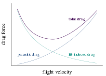
Induced drag must be added to the parasitic drag to find the total drag. Since induced drag is inversely proportional to the square of the airspeed (at a given lift) whereas parasitic drag is proportional to the square of the airspeed, the combined overall drag curve shows a minimum at some airspeed - the minimum drag speed (VMD). An aircraft flying at this speed is operating at its optimal aerodynamic efficiency. According to the above equations, the speed for minimum drag occurs at the speed where the induced drag is equal to the parasitic drag.[22] This is the speed at which for unpowered aircraft, optimum glide angle is achieved. This is also the speed for greatest range (although VMD will decrease as the plane consumes fuel and becomes lighter). The speed for greatest range (i.e., distance travelled) is the speed at which a straight line from the origin is tangent to the fuel flow rate curve. The curve of range versus airspeed is normally very flat and it is customary to operate at the speed for 99% best range since this gives about 5% greater speed for only 1% less range. (Of course, flying higher where the air is thinner will raise the speed at which minimum drag occurs, and so permits a faster voyage for the same amount of fuel. If the plane is flying at the maximum permissible speed, then there is an altitude at which the air density will be what is needed to keep it aloft while flying at the angle of attack that minimizes the drag. The optimum altitude at maximum speed, and the optimum speed at maximum altitude, may change during the flight as the plane becomes lighter.)
The speed for maximum endurance (i.e., time in the air) is the speed for minimum fuel flow rate, and is less than the speed for greatest range. The fuel flow rate is calculated as the product of the power required and the engine specific fuel consumption (fuel flow rate per unit of power[23]). The power required is equal to the drag times the speed.
See also[]
References[]
- L. J. Clancy (1975), Aerodynamics, Pitman Publishing Limited, London. ISBN 0-273-01120-0
- Abbott, Ira H., and Von Doenhoff, Albert E. (1959), Theory of Wing Sections, Dover Publications, Standard Book Number 486-60586-8
- Luciano Demasi, Antonio Dipace, Giovanni Monegato, and Rauno Cavallaro. Invariant Formulation for the Minimum Induced Drag Conditions of Nonplanar Wing Systems, AIAA Journal, Vol. 52, No. 10 (2014), pp. 2223–2240. doi: 10.2514/1.J052837
Notes[]
- ^ Bjorn Fehrm (Nov 3, 2017). "Bjorn's Corner: Aircraft drag reduction, Part 3". Leeham.
- ^ a b McLean, Doug (2005). Wingtip Devices: What They Do and How They Do It (PDF). 2005 Boeing Performance and Flight Operations Engineering Conference. p. 4.4.
While the air more than about one wingspan ahead of the wing is essentially undisturbed, the general flow pattern of Figure 3.1 reaches practically full strength at a distance of about one wingspan behind the wing and generally persists over long distances downstream. At the location of the wing itself, the flow pattern has reached roughly half of its maximum strength, and the wing is flying through air that is already moving generally downward between the wingtips. Thus the wing can be thought of as flying in a downdraft of its own making. Because of the apparent downdraft, or "downwash," the total apparent lift vector is tilted backward slightly. It is the backward component of the apparent lift that is felt as induced drag.
- ^ a b McLean, Doug (2012). "8.1.1". Understanding Aerodynamics: Arguing from the Real Physics. ISBN 978-1119967514.
- ^ a b McLean, Doug (2005). Wingtip Devices: What They Do and How They Do It (PDF). 2005 Boeing Performance and Flight Operations Engineering Conference. p. 4.6.
The induction myth is more complicated and involves a serious misunderstanding of cause and effect. The trailing vortex sheet and the rolled-up vortex cores are often talked about as if they were the direct cause of the velocities everywhere else in the flowfield, and of induced drag, but this is misleading. It is true that in order for the large-scale flow pattern of Figure 3.1 to exist, there must be a vortex sheet shed from the trailing edge, but the vortex sheet is not a direct physical cause of the large-scale flow; it is more of a manifestation.
- ^ a b McLean, Doug (2012). "8.1.4, 8.3, 8.4.1". Understanding Aerodynamics: Arguing from the Real Physics. ISBN 978-1119967514. Doug McLean, Common Misconceptions in Aerodynamics on YouTube
- ^ a b McLean, Doug (2005). Wingtip Devices: What They Do and How They Do It. 2005 Boeing Performance and Flight Operations Engineering Conference. p. 4.7.
The induction myth leads us to think of induced drag as being "caused" by the vortex wake, and thus to think that by doing something very local to change the flow in the core of the “tip vortex” we can have a large effect on the induced drag.
- ^ Hurt, H. H. (1965) Aerodynamics for Naval Aviators, Figure 1.30, NAVWEPS 00-80T-80
- ^ Clancy, L.J. (1975) Aerodynamics Fig 5.24. Pitman Publishing Limited, London. ISBN 0-273-01120-0
- ^ Kermode, A.C. (1972). Mechanics of Flight, Figure 3.29, Ninth edition. Longman Scientific & Technical, England. ISBN 0-582-42254-X
- ^ Clancy, L.J., Aerodynamics, Section 5.3
- ^ Abbott, Ira H., and Von Doenhoff, Albert E., Theory of Wing Sections, Section 1.2 and Appendix IV
- ^ Clancy, L.J., Aerodynamics, Section 5.14
- ^ a b Clancy, L.J., Aerodynamics, Section 5.17
- ^ Anderson, John D. (2005), Introduction to Flight, McGraw-Hill. ISBN 0-07-123818-2. p318
- ^ McLean, Doug (2005). Wingtip Devices: What They Do and How They Do It (PDF). 2005 Boeing Performance and Flight Operations Engineering Conference. p. 4.10.
Based on our general appreciation of the physics, we can anticipate that drag-reduction devices need to be fairly large as viewed in the Trefftz plane, since any significant reduction in induced drag requires changing the global flowfield associated with the lift, so as to reduce its total kinetic energy. We know that we can’t do this just by tinkering with the "tip vortex" and thus that having a significant effect on the drag requires a significant change in the way the lift is distributed spatially. If our starting point is a wing on which the lift is already advantageously distributed, the only way to improve will be to provide a significant increase in the horizontal span or to introduce a nonplanar element that has a similar effect.
- ^ McLean, Doug (2005). Wingtip Devices: What They Do and How They Do It. 2005 Boeing Performance and Flight Operations Engineering Conference. p. 4.10.
Trefftz-plane theory tells us that we can reduce the ideal induced drag by increasing the vertical height of the lifting system, as well as by increasing the horizontal span. A vertical fin or winglet that adds vertical height to the system will reduce the ideal induced drag if it is placed anywhere along the span of the wing off of the airplane center plane, but it is most effective by far when it is placed at the station of maximum span; that is, at the tip.
- ^ Richard T. Witcomb (July 1976). A design approach and selected wind-tunnel results at high subsonic speeds for wing-tip mounted winglets (PDF) (Technical report). NASA. 19760019075. p. 1:
Winglets, which are small, nearly vertical, winglike surfaces mounted at the tips of a wing, are intended to provide, for lifting conditions and subsonic Mach numbers, reductions in drag coefficient greater than those achieved by a simple wing-tip extension with the same structural weight penalty.
{{cite techreport}}: CS1 maint: date and year (link) - ^ Glauert, H. The Elements of Aerofoil and Airscrew Theory (1926); referenced in Fig. 5.4 of Airplane Aerodynamics by Daniel O. Dommasch, Sydney S. Sherby, Thomas F. Connolly, 3rd ed. (1961)
- ^ McLean, Doug (2005). Wingtip Devices: What They Do and How They Do It. 2005 Boeing Performance and Flight Operations Engineering Conference. p. 4.9.
The well-known elliptic spanload is "ideal" for a planar (flat) wing. For nonplanar configurations, the ideal spanload is not generally elliptic, but it is easily calculated for a given geometry. With a vertical winglet added, for example, the ideal spanload shows less lift inboard and more lift outboard, relative to elliptic, with a certain, optimum distribution on the winglet itself, as shown in Figure 3.5.
- ^ McLean, Doug (2005). Wingtip Devices: What They Do and How They Do It. 2005 Boeing Performance and Flight Operations Engineering Conference. p. 4.9.
Relative to these "ideal" spanloads, the spanloads used on real wings are usually modified somewhat to reduce bending loads and allow a lighter wing structure, at the expense of a slight increase in drag. The presence a fuselage and wing-mounted engines also tends to alter the spanload on real wings.
- ^ "Induced Drag". Retrieved 5 May 2015.
- ^ Clancy, L.J., Aerodynamics, Section 5.25
- ^ The engine specific fuel consumption is normally expressed in units of fuel flow rate per unit of thrust or per unit of power depending on whether the engine output is measured in thrust, as for a jet engine, or shaft horsepower, as for a propeller engine. To convert fuel rate per unit thrust to fuel rate per unit power one must divide by the speed.
- Drag (physics)