Möbius–Kantor polygon
| Möbius–Kantor polygon | |
|---|---|
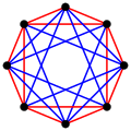
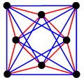
Orthographic projection shown here with 4 red and 4 blue 3-edge triangles. | |
| Shephard symbol | 3(24)3 |
| Schläfli symbol | 3{3}3 |
| Coxeter diagram | |
| Edges | 8 3{} |
| Vertices | 8 |
| Petrie polygon | Octagon |
| Shephard group | 3[3]3, order 24 |
| Dual polyhedron | Self-dual |
| Properties | Regular |
In geometry, the Möbius–Kantor polygon is a regular complex polygon 3{3}3, ![]()
![]()
![]() , in . 3{3}3 has 8 vertices, and 8 edges. It is self-dual. Every vertex is shared by 3 triangular edges.[1] Coxeter named it a Möbius–Kantor polygon for sharing the complex configuration structure as the Möbius–Kantor configuration, (83).[2]
, in . 3{3}3 has 8 vertices, and 8 edges. It is self-dual. Every vertex is shared by 3 triangular edges.[1] Coxeter named it a Möbius–Kantor polygon for sharing the complex configuration structure as the Möbius–Kantor configuration, (83).[2]
Discovered by G.C. Shephard in 1952, he represented it as 3(24)3, with its symmetry, Coxeter called as 3[3]3, isomorphic to the binary tetrahedral group, order 24.
Coordinates[]
The 8 vertex coordinates of this polygon can be given in , as:
| (ω,−1,0) | (0,ω,−ω2) | (ω2,−1,0) | (−1,0,1) |
| (−ω,0,1) | (0,ω2,−ω) | (−ω2,0,1) | (1,−1,0) |
where .
As a Configuration[]
The configuration matrix for 3{3}3 is:[3]
Real representation[]
It has a real representation as the 16-cell, ![]()
![]()
![]()
![]()
![]()
![]()
![]() , in 4-dimensional space, sharing the same 8 vertices. The 24 edges in the 16-cell are seen in the Möbius–Kantor polygon when the 8 triangular edges are drawn as 3-separate edges. The triangles are represented 2 sets of 4 red or blue outlines. The B4 projections are given in two different symmetry orientations between the two color sets.
, in 4-dimensional space, sharing the same 8 vertices. The 24 edges in the 16-cell are seen in the Möbius–Kantor polygon when the 8 triangular edges are drawn as 3-separate edges. The triangles are represented 2 sets of 4 red or blue outlines. The B4 projections are given in two different symmetry orientations between the two color sets.
| Plane | B4 | F4 | |
|---|---|---|---|
| Graph | 
|

|

|
| Symmetry | [8] | [12/3] | |
Related polytopes[]
 This graph shows the two alternated polygons as a compound in red and blue 3{3}3 in dual positions. |
 3{6}2, |
It can also be seen as an alternation of ![]()
![]()
![]() , represented as
, represented as ![]()
![]()
![]() .
. ![]()
![]()
![]() has 16 vertices, and 24 edges. A compound of two, in dual positions,
has 16 vertices, and 24 edges. A compound of two, in dual positions, ![]()
![]()
![]() and
and ![]()
![]()
![]() , can be represented as
, can be represented as ![]()
![]()
![]() , contains all 16 vertices of
, contains all 16 vertices of ![]()
![]()
![]() .
.
The truncation ![]()
![]()
![]() , is the same as the regular polygon, 3{6}2,
, is the same as the regular polygon, 3{6}2, ![]()
![]()
![]() . Its edge-diagram is the cayley diagram for 3[3]3.
. Its edge-diagram is the cayley diagram for 3[3]3.
The regular Hessian polyhedron 3{3}3{3}3, ![]()
![]()
![]()
![]()
![]() has this polygon as a facet and vertex figure.
has this polygon as a facet and vertex figure.
Notes[]
References[]
- Shephard, G.C.; Regular complex polytopes, Proc. London math. Soc. Series 3, Vol 2, (1952), pp 82–97.
- Coxeter, H. S. M. and Moser, W. O. J.; Generators and Relations for Discrete Groups (1965), esp pp 67–80.
- Coxeter, H. S. M.; Regular Complex Polytopes, Cambridge University Press, (1974), second edition (1991).
- Coxeter, H. S. M. and Shephard, G.C.; Portraits of a family of complex polytopes, Leonardo Vol 25, No 3/4, (1992), pp 239–244 [1]
- Polytopes
- Complex analysis


![{\displaystyle \left[{\begin{smallmatrix}8&3\\3&8\end{smallmatrix}}\right]}](https://wikimedia.org/api/rest_v1/media/math/render/svg/b37f4763f271663fad46763e02ee9eb6320ae704)