Nodal analysis
In electric circuits analysis, nodal analysis, node-voltage analysis, or the branch current method is a method of determining the voltage (potential difference) between "nodes" (points where elements or branches connect) in an electrical circuit in terms of the branch currents.
In analyzing a circuit using Kirchhoff's circuit laws, one can either do nodal analysis using Kirchhoff's current law (KCL) or mesh analysis using Kirchhoff's voltage law (KVL). Nodal analysis writes an equation at each electrical node, requiring that the branch currents incident at a node must sum to zero. The branch currents are written in terms of the circuit node voltages. As a consequence, each branch constitutive relation must give current as a function of voltage; an admittance representation. For instance, for a resistor, Ibranch = Vbranch * G, where G (=1/R) is the admittance (conductance) of the resistor.
Nodal analysis is possible when all the circuit elements' branch constitutive relations have an admittance representation. Nodal analysis produces a compact set of equations for the network, which can be solved by hand if small, or can be quickly solved using linear algebra by computer. Because of the compact system of equations, many circuit simulation programs (e.g., SPICE) use nodal analysis as a basis. When elements do not have admittance representations, a more general extension of nodal analysis, modified nodal analysis, can be used.
Procedure[]
- Note all connected wire segments in the circuit. These are the nodes of nodal analysis.
- Select one node as the ground reference. The choice does not affect the element voltages (but it does affect the nodal voltages) and is just a matter of convention. Choosing the node with the most connections can simplify the analysis. For a circuit of N nodes the number of nodal equations is N−1.
- Assign a variable for each node whose voltage is unknown. If the voltage is already known, it is not necessary to assign a variable.
- For each unknown voltage, form an equation based on Kirchhoff's Current Law (i.e. add together all currents leaving from the node and mark the sum equal to zero). The current between two nodes is equal to the voltage of the node where the current exits minus the voltage of the node where the current enters the node, both divided by the resistance between the two nodes.
- If there are voltage sources between two unknown voltages, join the two nodes as a supernode. The currents of the two nodes are combined in a single equation, and a new equation for the voltages is formed.
- Solve the system of simultaneous equations for each unknown voltage.
Examples[]
Basic case[]

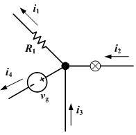
The only unknown voltage in this circuit is . There are three connections to this node and consequently three currents to consider. The direction of the currents in calculations is chosen to be away from the node.

- Current through resistor :
- Current through resistor :
- Current through current source :


With Kirchhoff's current law, we get:

This equation can be solved with respect to V1:

Finally, the unknown voltage can be solved by substituting numerical values for the symbols. Any unknown currents are easy to calculate after all the voltages in the circuit are known.

Supernodes[]

In this circuit, we initially have two unknown voltages, V1 and V2. The voltage at V3 is already known to be VB because the other terminal of the voltage source is at ground potential.
The current going through voltage source VA cannot be directly calculated. Therefore, we cannot write the current equations for either V1 or V2. However, we know that the same current leaving node V2 must enter node V1. Even though the nodes cannot be individually solved, we know that the combined current of these two nodes is zero. This combining of the two nodes is called the supernode technique, and it requires one additional equation: V1 = V2 + VA.
The complete set of equations for this circuit is:

By substituting

Matrix form for the node-voltage equation[]
In general, for a circuit with nodes, the node-voltage equations obtained by nodal analysis can be written in a matrix form as derived in the following. For any node , KCL states where is the negative of the sum of the conductances between nodes and , and is the voltage of node . This implies where is the sum of conductances connected to node . We note that the first term contributes linearly to the node via , while the second term contributes linearly to each node connected to the node via with a minus sign. If an independent current source/input is also attached to node , the above expression is generalized to . It is readily shown that one can combine the above node-voltage equations for all nodes, and write them down in the following matrix form


The matrix on the left hand side of the equation is singular since it satisfies where is a column matrix. This corresponds to the fact of current conservation, namely, , and the freedom to choose a reference node (ground). In practice, the voltage is the reference node is taken to be 0. Consider it is the last node, . In this case, it is straightforward to verify that the resulting equations for the other nodes remain the same, and therefore one can simply discard the last column as well as the last line of the matrix equation. This procedure results in a dimensional non-singular matrix equation with the definitions of all the elements stay unchanged.


See also[]
References[]
- P. Dimo Nodal Analysis of Power Systems Abacus Press Kent 1975
External links[]
| Wikiversity has learning resources about Nodal analysis |
- Electronic circuits
- Electrical engineering