Rotary friction welding
Rotary friction welding (RFW) one of the methods of friction welding, the classic way of which uses the work of friction to create a not separable weld. Typically one welded element is rotated to the other and forge (pressed down by axial force). The heating of the material is caused by friction work and creates a permanent connection. In this method can be welded the same, dissimilar, or composite[1] and non-metallic materials. The friction welding methods of are often considered as solid-state welding.
History[]

Some applications and patents connected with friction welding were dated back to the turn of the century[2] and rotary friction welding is the oldest of these methods.[3] W. Richter patented the method of linear friction welding (LFW) process in 1924 in England and 1929 in Germany, however, the description of the process was vague[3] and H.Klopstock patented the same process in the USSR 1924.[4] But first description and experiments related to rotary friction welding took place in the Soviet Union in 1956,[2][4] machinist named A. J. Chdikov (А. И. Чудиков[5]) has realized scientific studies and suggested the use of this welding method as a commercial process[4] at first he discovered the method by accident in Elbrussky mine where he worked, he did not pay enough attention and not lubricate the lathe chuck inside and then it turned out that he had welded the workpiece to the lathe.[5] He wondered if this accident can be used for joining and came to conclusion that it was necessary to work at high rotation speeds (in these times about 1000 turnover per second), immediately brake and press down welded components.[5] He decided to write a letter to the Ministry of Metallurgy and received the answer that this welding was inappropriate, but small note about the method was published in the newspaper and aroused interest with Yu. Ya. Terentyeva who was manager in Scientific Research Institute of Electrical Welding Equipment, and with time his method was disseminated.[5] The process was introduced to the USA in 1960.[2] The American companies Caterpillar Tractor Company (Caterpillar - CAT), Rockwell International, and American Manufacturing Foundry all developed machines for this process. Patents were also issued throughout Europe and the former Soviet Union. The first studies of friction welding in England were carried out by the Welding Institute in 1961.[4] The USA with Caterpillar Tractor Company and MTI developed an inertia process in 1962.[2][4] Europe with KUKA AG and Thompson launches rotary friction welding for industrial applications in 1966, developed a direct-drive process and in 1974 builds rRS6 the double spindle machine for heavy truck axles.[6][7] In 1997, international patent application was filed entitled “Method of Friction Welding Tubular Members”, A. Graham was presented welding pipes with a diameter of 152.4 mm a method that uses radial friction welding with an intermediate ring for connect long pipes,[8][9] but some attempts occurred earlier in 1975 through methods called radial friction welding (RF),[10] and even earlier, for example specialists from Leningrad mention about possibility of use ring to connect long components and it was written before the 1960s in newspaper.[5] Another method was invented and experimentally proven at The Welding Institute (TWI) in the UK and patented in 1991 Friction stir welding (FSW) process.[11] In 2008 KUKA AG developed the rotary friction welding machine SRS 1000 with a forged force of 1000 tons.[6] An improved modification is also Low Force Friction Welding, hybrid technology developed by EWI and Manufacturing Technology Inc. (MTI), the process can apply to both linear and rotary friction welding.[12] Based on information from 2020 year only KUKA has been operating in 44 country and has initiated more than 1200 systems[6][13] also for subcontract facility[14] however there are more companies in the world and for example the The Welding Institute TWI have more than 50 years expertise and insight inherent to process development.[15] However, there are more companies not every is promoted but today, friction welding is conducted worldwide with various materials both in scientific studies and industrial applications.
Applications[]
Rotary friction welding is widely implemented across the manufacturing sector and has been used for numerous applications,[16][17] including:
- Parts in gas turbine such as: turbine shafts, turbine discs, compressor drums,[18]
- Automotive parts including steel truck axles and casings, hollow valve, motor hollow pistons, passenger car wheel rims, converter for passenger car automatic gears,
- Turbine for aircraft engine,[19]
- Monel to steel marine fittings,
- Piston rods,
- Copper - aluminium electrical connections,
- Heat exchangers,
- Cutting tools,
- Drill pipes,[20]
- Reactor pressure vassels nozzles,[18]
- Tubular transition joints combining dissimilar metals (Aluminium - Titanium and Aluminium - Stainless steel),
- Potential for medical applications,[21]
- For learning students at technical universities.
Connections geometry[]
Rotary Friction Welding can join a wide range of part geometries Typically: Tube to Tube, Tube to Plate, Tube to Bar, Tube to Disk, Bar to Bar, Bar to Plate and in addition, to this a rotating ring is used to connect long components.[23]
Geometry of the component surface not is not always flat for example it can be conical surface and not only.[24]
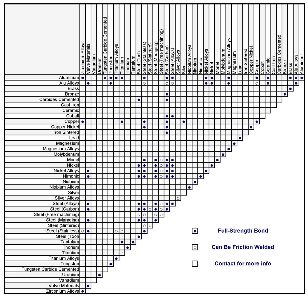
Types of materials to be welded[]
In rotary friction welding enables to weld various materials. Metallic materials of the same name or dissimilar either composite,[1] superalloys[25] and non-metallic e.g. thermoplastic polymers[26] can be welded and even welding of wood is investigated.[27] Weldability tables of metallic alloy can be found on the Internet and in books.[22] Sometimes an interlayer is used to connect non-compatible materials.[21][28]

Rotary friction welding for plastics[]
Friction welding is also used to join thermoplastic components.[26]
Division due to drive motor[]
In direct-drive friction welding (also called continuous drive friction welding) the drive motor and chuck are connected. The drive motor is continually driving the chuck during the heating stages. Usually, a clutch is used to disconnect the drive motor from the chuck, and a brake is then used to stop the chuck.

In inertia friction welding the drive motor is disengaged, and the workpieces are forced together by a friction welding force. The kinetic energy stored in the rotating flywheel is dissipated as heat at the weld interface as the flywheel speed decreases. Before welding, one of the workpieces is attached to the rotary chuck along with a flywheel of a given weight. The piece is then spun up to a high rate of rotation to store the required energy in the flywheel. Once spinning at the proper speed, the motor is removed and the pieces forced together under pressure. The force is kept on the pieces after the spinning stops to allow the weld to "set".[23]
Stages of process[]

- Step 1 and 2, friction stage: one of the component is set in rotation, and then pressed to the other stationary one in axial of rotation,
- Step 3, braking stage: the rotating component is stopped in braking time,
- Step 4, upsetting stage: the welded elements are still forging by forge pressure (pressed down),
- Step 5: in standard RFW welding (standard parameters), a flash will be created. Flash can be cut off on the welder.[29]

However, referring to the stages chart:
- modifications of the process exist,
- may depend on the version of the process: direct-drive, inertia friction welding, hybryd welding,[18]
- there are many versions of welding machines,
- many materials can are welded with not the same properties, with various geometries,
- the real life process does not have to match to the ideal settings on the welding machine.
RFW Friction work on cylindrical rods workpieces[]
This section needs expansion. You can help by . (December 2020) |
Friction work create weld and can believe that is calculated for cylindrical workpieces from math:
Work:
(1)

Moment of force M general formula:
(2)

The force F will be the frictional force T (F=T) so substituting for the formula (2):
(3)

The friction force T will be the pressure F times by the friction coefficient µ:
(4)

So moment of force M:
(5)

The alpha angle that each point will move with the axis of rotating cylindrical workpieces will be:
(6)

So friction work:
(7) [verification needed]

For variable value μ over friction time:
(8)

This requires verification but from equation it appears that turnover and force (or pressure no surface ) is linear to friction work (W) so for example if pressure increase 2 times then fricrion work also increase 2 times, if turnover increase 2 times then fricrion work also increase 2 times and referring to rules conservation of energy this can heat 2 times more the material to the same temperature or the temperature may increase 2 times. Hovewer pressure has the same effect over the entire surface but rotation have more impact away from the axis of rotation because it is a rotary motion. Referring to thermal conductivity the friction time affects to the flash size when shorter time was used then friction work is more concentrated in a smaller area.[verification needed]

or variable values μ, n, F over friction time:
(9) [verification needed]

- t [s]- time of friction (when piece rotary),
- μ - coefficient of friction,
- F [N]- pressure force,
- r [m]- radius of workpiece,
- n [1/s] - turnover per second,
- W [J] - friction work.

Therefore, the calculation in this way is not reliable in real is complicated. An example article considering the variable depends on the temperature coefficient of friction steel - aluminum Al60611 - Alumina is described by authors from Malaysia in for example this paper "Evaluation of Properties and FEM Model of the Friction Welded Mild Steel-Al6061-Alumina"[34] and based on this position someone created no step by step but whatever an instructional simulation video in abaqus software and in this paper is possible to find the selection of the mesh type in the simulation described by the authors and there are some instructions such as use the Johnson-Cook material model choice, and not only, there is dissipation coefficient value, friction welding condition, the article included too the physical formulas related to rotary friction welding described by the authors such as: heat transfer equation and convection in rods, equations related to deformation processes.[34] Article included information on the parameters of authors research, but it is not a step by step and simple instruction such as also the video and good add that it is not the only one position in literature. The conclusion include information that: "Even though the FE model proposed in this study cannot replace a more accurate analysis, it does provide guidance in weld parameter development and enhances understanding of the friction welding process, thus reducing costly and time consuming experimental approaches."[34]
The coefficient of friction changes with temperature and there are a number of factors internal friction (viscosity - e.g. Dynamic viscosity according to Carreau's fluid law[35]), forge, properties of the material during welding are variable, also there is plastic deformation.
Carreau's fluid law:
Generalized Newtonian fluid where viscosity, , depends upon the shear rate, , by the following equation:


(10)

Where:
- , , and are material coefficients.
- = viscosity at zero shear rate (Pa.s)
- = viscosity at infinite shear rate (Pa.s)
- = relaxation time (s)
- = power index


Modelling of the frictional heat generated within the RFW process can be realized as a function of conducted frictional work and its dissipation coefficient, incremental frictional work of a node