STL (file format)
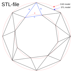 A CAD representation of a torus (shown as two concentric red circles) and an STL approximation of the same shape (composed of triangular planes) | |
| Filename extension |
.stl |
|---|---|
| Internet media type |
|
| Developed by | 3D Systems |
| Initial release | 1987 |
| Type of format | Stereolithography |
STL is a file format native to the stereolithography CAD software created by 3D Systems.[1][2][3] STL has several backronyms such as "Standard Triangle Language" and "Standard Tessellation Language".[4] This file format is supported by many other software packages; it is widely used for rapid prototyping, 3D printing and computer-aided manufacturing.[5] STL files describe only the surface geometry of a three-dimensional object without any representation of color, texture or other common CAD model attributes. The STL format specifies both ASCII and binary representations. Binary files are more common, since they are more compact.[6]
An STL file describes a raw, unstructured triangulated surface by the unit normal and vertices (ordered by the right-hand rule) of the triangles using a three-dimensional Cartesian coordinate system. In the original specification, all STL coordinates were required to be positive numbers, but this restriction is no longer enforced and negative coordinates are commonly encountered in STL files today. STL files contain no scale information, and the units are arbitrary.[7]
ASCII STL[]
An ASCII STL file begins with the line
solid name
where name is an optional string (though if name is omitted there must still be a space after solid). The file continues with any number of triangles, each represented as follows:
facet normal ni nj nk
    outer loop
        vertex v1x v1y v1z
        vertex v2x v2y v2z
        vertex v3x v3y v3z
    endloop
endfacet
where each n or v is a floating-point number in sign-mantissa-"e"-sign-exponent format, e.g., "2.648000e-002". The file concludes with
endsolid name

The structure of the format suggests that other possibilities exist (e.g., facets with more than one "loop", or loops with more than three vertices). In practice, however, all facets are simple triangles.
White space (spaces, tabs, newlines) may be used anywhere in the file except within numbers or words. The spaces between "facet" and "normal" and between "outer" and "loop" are required.[6]
Binary STL[]
Because ASCII STL files can be very large, a binary version of STL exists. A binary STL file has an 80-character header (which is generally ignored, but should never begin with "solid" because that may lead some software to assume that this is an ASCII STL file). Following the header is a 4-byte little-endian unsigned integer indicating the number of triangular facets in the file. Following that is data describing each triangle in turn. The file simply ends after the last triangle.
Each triangle is described by twelve 32-bit floating-point numbers: three for the normal and then three for the X/Y/Z coordinate of each vertex – just as with the ASCII version of STL. After these follows a 2-byte ("short") unsigned integer that is the "attribute byte count" – in the standard format, this should be zero because most software does not understand anything else.[6]
Floating-point numbers are represented as IEEE floating-point numbers and are assumed to be little-endian, although this is not stated in documentation.
UINT8[80]    – Header                 -     80 bytes
UINT32       – Number of triangles    -      4 bytes

foreach triangle                      - 50 bytes:
    REAL32[3] – Normal vector             - 12 bytes
    REAL32[3] – Vertex 1                  - 12 bytes
    REAL32[3] – Vertex 2                  - 12 bytes
    REAL32[3] – Vertex 3                  - 12 bytes
    UINT16    – Attribute byte count      -  2 bytes
end
Color in binary STL[]
There are at least two non-standard variations on the binary STL format for adding color information:
- The VisCAM and SolidView software packages use the two "attribute byte count" bytes at the end of every triangle to store a 15-bit RGB color:
- bits 0 to 4 are the intensity level for blue (0 to 31),
- bits 5 to 9 are the intensity level for green (0 to 31),
- bits 10 to 14 are the intensity level for red (0 to 31),
- bit 15 is 1 if the color is valid, or 0 if the color is not valid (as with normal STL files).
- The Materialise Magics software uses the 80-byte header at the top of the file to represent the overall color of the entire part. If color is used, then somewhere in the header should be the ASCII string "COLOR=" followed by four bytes representing red, green, blue and alpha channel (transparency) in the range 0–255. This is the color of the entire object, unless overridden at each facet. Magics also recognizes a material description; a more detailed surface characteristic. Just after "COLOR=RGBA" specification should be another ASCII string ",MATERIAL=" followed by three colors (3×4 bytes): first is a color of diffuse reflection, second is a color of specular highlight, and third is an ambient light. Material settings are preferred over color. The per-facet color is represented in the two "attribute byte count" bytes as follows:
- bits 0 to 4 are the intensity level for red (0 to 31),
- bits 5 to 9 are the intensity level for green (0 to 31),
- bits 10 to 14 are the intensity level for blue (0 to 31),
- bit 15 is 0 if this facet has its own unique color, or 1 if the per-object color is to be used.
The red/green/blue ordering within those two bytes is reversed in these two approaches – so while these formats could easily have been compatible, the reversal of the order of the colors means that they are not – and worse still, a generic STL file reader cannot automatically distinguish between them. There is also no way to have facets be selectively transparent because there is no per-facet alpha value – although in the context of current rapid prototyping machinery, this is not important.
The facet normal[]
In both ASCII and binary versions of STL, the facet normal should be a unit vector pointing outwards from the solid object.[8] In most software this may be set to (0,0,0), and the software will automatically calculate a normal based on the order of the triangle vertices using the "right-hand rule", i.e. the vertices are listed in counter-clock-wise order from outside. Some STL loaders (e.g. the STL plugin for Art of Illusion) check that the normal in the file agrees with the normal they calculate using the right-hand rule and warn the user when it does not. Other software may ignore the facet normal entirely and use only the right-hand rule. Although it is rare to specify a normal that cannot be calculated using the right-hand rule, in order to be entirely portable, a file should both provide the facet normal and order the vertices appropriately. A notable exception is SolidWorks, which uses the normal for shading effects.
Use in 3D printing[]

3D printers build objects by solidifying (SLA, SLS, SHS, DMLS, EBM, DLP) or printing (3DP, MJM, FDM, FFF, PJP, MJS)[9] one layer at a time. This requires a series of closed 2D contours (horizontal layers) that are filled in with solidified material as the layers are fused together. A natural file format for such a machine would be a series of closed polygons (layers or slices) corresponding to different Z-values. However, since it is possible to vary the layer thicknesses for a faster though less precise build, it was easier to define the model to be built as a closed polyhedron that can be sliced at the necessary horizontal levels. An incorrect facet normal can affect the way a file is sliced and filled. A slice at a different Z-value can be chosen to miss a bad facet or the file must be returned to CAD program to make corrections and then regenerate the STL file.
The STL file format appears capable of defining a polyhedron with any polygonal facet, but in practice it is only ever used for triangles, which means that much of the syntax of the ASCII protocol is superfluous.
To properly form a 3D volume, the surface represented by any STL files must be closed (no holes or reversed vector normal) and connected, where every edge is part of exactly two triangles, and not self-intersecting. Since the STL syntax does not enforce this property, it can be ignored for applications where the void does not matter. The missing surface only matters insofar as the software that slices the triangles requires it to ensure that the resulting 2D polygons are closed. Sometimes such software can be written to clean up small discrepancies by moving vertices that are close together so that they coincide. The results are not predictable, may be sufficient of the surface must be repaired using another program. Vector 3D printers require a clean .STL file and printing a bad data file will either fail to fill or may stop printing.
Use in other fields[]

STL file format is simple and easy to output. Consequently, many computer-aided design systems can output the STL file format. Although the output is simple to produce, mesh connectivity information is discarded because the identity of shared vertices is lost.
Many computer-aided manufacturing systems require triangulated models. STL format is not the most memory- and computationally efficient method for transferring this data, but STL is often used to import the triangulated geometry into the CAM system. The format is commonly available, so the CAM system will use it. In order to use the data, the CAM system may have to reconstruct the connectivity. As STL files do not save the physical dimension of a unit, a CAM system will ask for it. Typical units are mm and inch.
STL can also be used for interchanging data between CAD/CAM systems and computational environments such as Mathematica.
Representation of curved surfaces[]
It is not possible to use triangles to perfectly represent curved surfaces. To compensate, users often save enormous STL files to reduce the inaccuracy. However, native formats associated with many 3D design software use mathematical surfaces to preserve detail losslessly in small files. For example, Rhino 3D[10] and Blender[11] implement NURBS to create true curved surfaces and store them in their respective native file formats, but must generate a triangle mesh when exporting a model to the STL format.
History[]
STL was invented by the Albert Consulting Group for 3D Systems in 1987.[12] The format was developed for 3D Systems' first commercial 3D printers. Since its initial release, the format remained relatively unchanged for 22 years.[13]
In 2009, an update to the format, dubbed STL 2.0, was proposed. It evolved into the Additive manufacturing file format.[13][14]
See also[]
- 3D Manufacturing Format (3MF), a standard for 3D file manufacturing
- Additive Manufacturing File Format (AMF), a standard with support for color, multiple materials, and constellations
- PLY (file format), an alternative file format
- Voxel
- Wavefront .obj file, a 3D geometry definition file format with .obj file extension
- X3D, a royalty-free ISO standard for 3D computer graphics
References[]
- ^ StereoLithography Interface Specification, 3D Systems, Inc., July 1988
- ^ StereoLithography Interface Specification, 3D Systems, Inc., October 1989
- ^ SLC File Specification, 3D Systems, Inc., 1994
- ^ Grimm, Todd (2004), User's Guide to Rapid Prototyping, Society of Manufacturing Engineers, p. 55, ISBN 0-87263-697-6. Many names are used for the format: for example, "standard triangle language", "stereolithography language", and "stereolithography tesselation language". Page 55 states, "Chuck Hull, the inventor of stereolithography and 3D Systems' founder, reports that the file extension is for stereolithography."
- ^ Chua, C. K; Leong, K. F.; Lim, C. S. (2003), Rapid Prototyping: Principles and Applications (2nd ed.), World Scientific Publishing Co, ISBN 981-238-117-1 Chapter 6, Rapid Prototyping Formats. Page 237, "The STL (STeroLithography) file, as the de facto standard, has been used in many, if not all, rapid prototyping systems." Section 6.2 STL File Problems. Section 6.4 STL File Repair.
- ^ Jump up to: a b c Burns, Marshall (1993). Automated Fabrication. Prentice Hall. ISBN 978-0-13-119462-5.
- ^ fabbers.com Historical resource on 3D printing, The StL Format: Standard Data Format for Fabbers, reprinted from Marshall Burns, Automated Fabrication, http://www.ennex.com/~fabbers/StL.asp stating, "The object represented must be located in the all-positive octant. In other words, all vertex coordinates must be positive-definite (nonnegative and nonzero) numbers. The StL file does not contain any scale information; the coordinates are in arbitrary units."
- ^ Peddie, Jon. (2013). The history of visual magic in computers : how beautiful images are made in CAD, 3D, VR and AR. London: Springer. pp. 54–57. ISBN 978-1-4471-4932-3. OCLC 849634980.
- ^ Barnatt, Christopher, 1967- (2013). 3D printing : the next industrial revolution. [Nottingham, England?]: ExplainingTheFuture.com. pp. 26–71. ISBN 978-1-4841-8176-8. OCLC 854672031.CS1 maint: multiple names: authors list (link)
- ^ "What are NURBS?". www.rhino3d.com. Retrieved 2021-06-25.
- ^ "Structure — Blender Manual". docs.blender.org. Retrieved 2021-06-25.
- ^ "STL File Format for 3D Printing - Explained in Simple Terms". All3DP. 17 November 2016. Retrieved 5 May 2017.
- ^ Jump up to: a b "STL 2.0 May Replace Old, Limited File Format". RapidToday. Retrieved 5 May 2017.
- ^ Hiller, Jonathan D.; Lipson, Hod (2009). STL 2.0: A Proposal for a Universal Multi-Material Additive Manufacturing File Format (PDF). Solid Freeform Fabrication Symposium (SFF'09). Austin, TX, USA: Cornell University. Archived from the original (PDF) on 2020-06-11. Retrieved 5 May 2017.
External links[]
- The STL Format - Standard Data Format for Fabbers
- CAD file formats
- 3D graphics file formats