Slip angle
This article needs additional citations for verification. (June 2018) |

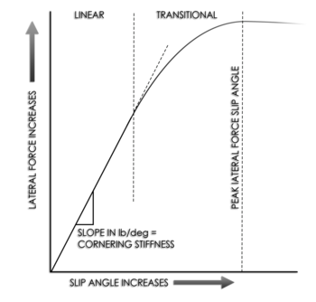
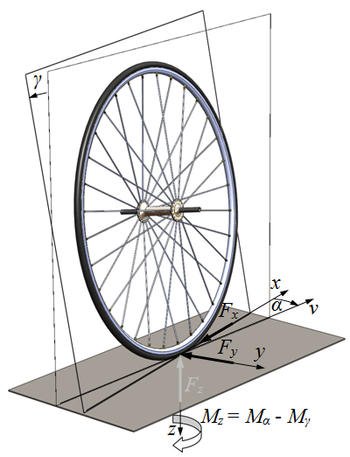


In vehicle dynamics, slip angle[1] or sideslip angle[2] is the angle between the direction in which a wheel is pointing and the direction in which it is actually traveling (i.e., the angle between the forward velocity vector and the vector sum of wheel forward velocity and lateral velocity , as defined in the image to the right).[1] This slip angle results in a force, the cornering force, which is in the plane of the contact patch and perpendicular to the intersection of the contact patch and the midplane of the wheel.[1] This cornering force increases approximately linearly for the first few degrees of slip angle, then increases non-linearly to a maximum before beginning to decrease.[1]


The slip angle, is defined as

Causes[]
A non-zero slip angle arises because of deformation in the tire carcass and tread. As the tire rotates, the friction between the contact patch and the road results in individual tread 'elements' (finite sections of tread) remaining stationary with respect to the road. If a side-slip velocity u is introduced, the contact patch will be deformed. When a tread element enters the contact patch, the friction between the road and the tire causes the tread element to remain stationary, yet the tire continues to move laterally. Thus the tread element will be ‘deflected’ sideways. While it is equally valid to frame this as the tire/wheel being deflected away from the stationary tread element, convention is for the co-ordinate system to be fixed around the wheel mid-plane.
While the tread element moves through the contact patch it is deflected further from the wheel mid-plane. This deflection gives rise to the slip angle, and to the cornering force. The rate at which the cornering force builds up is described by the relaxation length.
Effects[]
The ratios between the slip angles of the front and rear axles (a function of the slip angles of the front and rear tires respectively) will determine the vehicle's behavior in a given turn. If the ratio of front to rear slip angles is greater than 1:1, the vehicle will tend to understeer, while a ratio of less than 1:1 will produce oversteer.[2] Actual instantaneous slip angles depend on many factors, including the condition of the road surface, but a vehicle's suspension can be designed to promote specific dynamic characteristics. A principal means of adjusting developed slip angles is to alter the relative roll couple (the rate at which weight transfers from the inside to the outside wheel in a turn) front to rear by varying the relative amount of front and rear lateral load transfer. This can be achieved by modifying the height of the roll centers, or by adjusting , either through suspension changes or the addition of an anti-roll bar.
Because of asymmetries in the side-slip along the length of the contact patch, the resultant force of this side-slip occurs away from the geometric center of the contact patch, a distance described as the pneumatic trail, and so creates a torque on the tire, the so-called self aligning torque.
Measurement of slip angle[]
There are two main ways to measure slip angle of a tire: on a vehicle as it moves, or on a dedicated testing device.
There are a number of devices which can be used to measure slip angle on a vehicle as it moves; some use optical methods, some use inertial methods, some GPS and some both GPS and inertial.
Various test machines have been developed to measure slip angle in a controlled environment. A motorcycle tire test machine is located at the University of Padua. That uses a 3-meter diameter disk that rotates under a tire held at a fixed steer and camber angle, up to 54 degrees. Sensors measure the force and moment generated, and a correction is made to account for the curvature of the track.[2] Other devices use the inner or outer surface of rotating drums, sliding planks, conveyor belts, or a trailer that presses the test tire to an actual road surface.[1]
See also[]
- Camber thrust
- Cornering force
- Slip (vehicle dynamics)
- Traction circle
References[]
- Automotive safety
- Automotive steering technologies
- Automotive suspension technologies
- Tires
- Motorcycle dynamics