3D reconstruction
This article's factual accuracy may be compromised due to out-of-date information. (October 2019) |

In computer vision and computer graphics, 3D reconstruction is the process of capturing the shape and appearance of real objects. This process can be accomplished either by active or passive methods.[1] If the model is allowed to change its shape in time, this is referred to as reconstruction.[2]
Motivation and applications[]
The research of 3D reconstruction has always been a difficult goal. Using 3D reconstruction one can determine any object's 3D profile, as well as knowing the 3D coordinate of any point on the profile. The 3D reconstruction of objects is a generally scientific problem and core technology of a wide variety of fields, such as Computer Aided Geometric Design (CAGD), computer graphics, computer animation, computer vision, medical imaging, computational science, virtual reality, digital media, etc. For instance, the lesion information of the patients can be presented in 3D on the computer, which offers a new and accurate approach in diagnosis and thus has vital clinical value.[3] Digital elevation models can be reconstructed using methods such as airborne laser altimetry[4] or synthetic aperture radar.[5]
Active methods[]

Active methods, i.e. range data methods, given the depth map, reconstruct the 3D profile by numerical approximation approach and build the object in scenario based on model. These methods actively interfere with the reconstructed object, either mechanically or radiometrically using rangefinders, in order to acquire the depth map, e.g. structured light, laser range finder and other active sensing techniques. A simple example of a mechanical method would use a depth gauge to measure a distance to a rotating object put on a turntable. More applicable radiometric methods emit radiance towards the object and then measure its reflected part. Examples range from moving light sources, colored visible light, time-of-flight lasers [6] to microwaves or 3D ultrasound. See 3D scanning for more details.
Passive methods[]
Passive methods of 3D reconstruction do not interfere with the reconstructed object; they only use a sensor to measure the radiance reflected or emitted by the object's surface to infer its 3D structure through image understanding.[7] Typically, the sensor is an image sensor in a camera sensitive to visible light and the input to the method is a set of digital images (one, two or more) or video. In this case we talk about image-based reconstruction and the output is a 3D model. By comparison to active methods, passive methods can be applied to a wider range of situations.[8]
Monocular cues methods[]
Monocular cues methods refer to using one or more images from one viewpoint (camera) to proceed to 3D construction. It makes use of 2D characteristics(e.g. Silhouettes, shading and texture) to measure 3D shape, and that's why it is also named Shape-From-X, where X can be silhouettes, shading, texture etc. 3D reconstruction through monocular cues is simple and quick, and only one appropriate digital image is needed thus only one camera is adequate. Technically, it avoids stereo correspondence, which is fairly complex.[9]

Shape-from-shading Due to the analysis of the shade information in the image, by using Lambertian reflectance, the depth of normal information of the object surface is restored to reconstruct.[11]
Photometric Stereo This approach is more sophisticated than the shape-of-shading method. Images taken in different lighting conditions are used to solve the depth information. It is worth mentioning that more than one image is required by this approach.[12]
Shape-from-texture Suppose such an object with smooth surface covered by replicated texture units, and its projection from 3D to 2D causes distortion and perspective. Distortion and perspective measured in 2D images provide the hint for inversely solving depth of normal information of the object surface.[13]
Stereo vision[]
It has been suggested that this section be split out into another article titled Computer stereo vision. (Discuss) (December 2020) |
Stereo vision obtains the 3-dimensional geometric information of an object from multiple images based on the research of human visual system.[14] The results are presented in form of depth maps. Images of an object acquired by two cameras simultaneously in different viewing angles, or by one single camera at different time in different viewing angles, are used to restore its 3D geometric information and reconstruct its 3D profile and location. This is more direct than Monocular methods such as shape-from-shading.
Binocular stereo vision method requires two identical cameras with parallel optical axis to observe one same object, acquiring two images from different points of view. In terms of trigonometry relations, depth information can be calculated from disparity. Binocular stereo vision method is well developed and stably contributes to favorable 3D reconstruction, leading to a better performance when compared to other 3D construction. Unfortunately, it is computationally intensive, besides it performs rather poorly when baseline distance is large.
Problem statement and basics[]
The approach of using Binocular stereo vision to acquire object's 3D geometric information is on the basis of visual disparity.[15] The following picture provides a simple schematic diagram of horizontally sighted Binocular Stereo Vision, where b is the baseline between projective centers of two cameras.
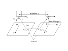
The origin of the camera's coordinate system is at the optical center of the camera's lens as shown in the figure. Actually, the camera's image plane is behind the optical center of the camera's lens. However, to simplify the calculation, images are drawn in front of the optical center of the lens by f. The u-axis and v-axis of the image's coordinate system are in the same direction with x-axis and y-axis of the camera's coordinate system respectively. The origin of the image's coordinate system is located on the intersection of imaging plane and the optical axis. Suppose such world point whose corresponding image points are and respectively on the left and right image plane. Assume two cameras are in the same plane, then y-coordinates of and are identical, i.e.,. According to trigonometry relations,


where are coordinates of in the left camera's coordinate system, is focal length of the camera. Visual disparity is defined as the difference in image point location of a certain world point acquired by two cameras,


based on which the coordinates of can be worked out.
Therefore, once the coordinates of image points is known, besides the parameters of two cameras, the 3D coordinate of the point can be determined.


The 3D reconstruction consists of the following sections:
Image acquisition[]
2D digital image acquisition is the information source of 3D reconstruction. Commonly used 3D reconstruction is based on two or more images, although it may employ only one image in some cases. There are various types of methods for image acquisition that depends on the occasions and purposes of the specific application. Not only the requirements of the application must be met, but also the visual disparity, illumination, performance of camera and the feature of scenario should be considered.
Camera calibration[]
Camera calibration in Binocular Stereo Vision refers to the determination of the mapping relationship between the image points and , and space coordinate in the 3D scenario. Camera calibration is a basic and essential part in 3D reconstruction via Binocular Stereo Vision.

Feature extraction[]
The aim of feature extraction is to gain the characteristics of the images, through which the stereo correspondence processes. As a result, the characteristics of the images closely link to the choice of matching methods. There is no such universally applicable theory for features extraction, leading to a great diversity of stereo correspondence in Binocular Stereo Vision research.
Stereo correspondence[]
Stereo correspondence is to establish the correspondence between primitive factors in images, i.e. to match and from two images. Certain interference factors in the scenario should be noticed, e.g. illumination, noise, surface physical characteristic, etc.
Restoration[]
According to precise correspondence, combined with camera location parameters, 3D geometric information can be recovered without difficulties. Due to the fact that accuracy of 3D reconstruction depends on the precision of correspondence, error of camera location parameters and so on, the previous procedures must be done carefully to achieve relatively accurate 3D reconstruction.
3D Reconstruction of medical images[]
Clinical routine of diagnosis, patient follow-up, computer assisted surgery, surgical planning etc. are facilitated by accurate 3D models of the desired part of human anatomy. Main motivation behind 3D reconstruction includes
- Improved accuracy due to multi view aggregation.
- Detailed surface estimates.
- Can be used to plan, simulate, guide, or otherwise assist a surgeon in performing a medical procedure.
- The precise position and orientation of the patient's anatomy can be determined.
- Helps in a number of clinical areas, such as radiotherapy planning and treatment verification, spinal surgery, hip replacement, neurointerventions and aortic stenting.
Applications:
3D reconstruction has applications in many fields. They are:
- Pavement engineering[6][16]
- Medicine[3]
- Free-viewpoint video reconstruction[17]
- Robotic mapping[18]
- City planning[19]
- Tomographic reconstruction[20]
- Gaming[21]
- Virtual environments and virtual tourism[21]
- Earth observation
- Archaeology[22]
- Augmented reality[23]
- Reverse engineering[24]
- Motion capture[25]
- 3D object recognition,[26] gesture recognition and hand tracking[27]
Problem Statement:
Mostly algorithms available for 3D reconstruction are extremely slow and cannot be used in real-time. Though the algorithms presented are still in infancy but they have the potential for fast computation.
Existing Approaches:

Delaunay and alpha-shapes
- Delaunay method involves extraction of tetrahedron surfaces from initial point cloud. The idea of ‘shape’ for a set of points in space is given by concept of alpha-shapes. Given a finite point set S, and the real parameter alpha, the alpha-shape of S is a polytope (the generalization to any dimension of a two dimensional polygon and a three-dimensional polyhedron) which is neither convex nor necessarily connected.[28] For a large value, the alpha-shape is identical to the convex-hull of S. The algorithm proposed by Edelsbrunner and Mucke[29] eliminates all tetrahedrons which are delimited by a surrounding sphere smaller than α. The surface is then obtained with the external triangles from the resulting tetrahedron.[29]
- Another algorithm called Tight Cocone[30] labels the initial tetrahedrons as interior and exterior. The triangles found in and out generate the resulting surface.
Both methods have been recently extended for reconstructing point clouds with noise.[30] In this method the quality of points determines the feasibility of the method. For precise triangulation since we are using the whole point cloud set, the points on the surface with the error above the threshold will be explicitly represented on reconstructed geometry.[28]

Zero set Methods
Reconstruction of the surface is performed using a distance function which assigns to each point in the space a signed distance to the surface S. A contour algorithm is used to extracting a zero-set which is used to obtain polygonal representation of the object. Thus, the problem of reconstructing a surface from a disorganized point cloud is reduced to the definition of the appropriate function f with a zero value for the sampled points and different to zero value for the rest. An algorithm called marching cubes established the use of such methods.[31] There are different variants for given algorithm, some use a discrete function f, while other use a polyharmonic radial basis function is used to adjust the initial point set.[32][33] Functions like Moving Least Squares, basic functions with local support,[34] based on the Poisson equation have also been used. Loss of the geometry precision in areas with extreme curvature, i.e., corners, edges is one of the main issues encountered. Furthermore, pretreatment of information, by applying some kind of filtering technique, also affects the definition of the corners by softening them. There are several studies related to post-processing techniques used in the reconstruction for the detection and refinement of corners but these methods increase the complexity of the solution.[35]

VR Technique
Entire volume transparence of the object is visualized using VR technique. Images will be performed by projecting rays through volume data. Along each ray, opacity and color need to be calculated at every voxel. Then information calculated along each ray will to be aggregated to a pixel on image plane. This technique helps us to see comprehensively an entire compact structure of the object. Since the technique needs enormous amount of calculations, which requires strong configuration computers is appropriate for low contrast data. Two main methods for rays projecting can be considered as follows:
- Object-order method: Projecting rays go through volume from back to front (from volume to image plane).
- Image-order or ray-casting method: Projecting rays go through volume from front to back (from image plane to volume).There exists some other methods to composite image, appropriate methods depending on the user's purposes. Some usual methods in medical image are MIP (maximum intensity projection), MinIP (minimum intensity projection), AC (alpha compositing) and NPVR (non-photorealistic volume rendering).
Voxel Grid
In this filtering technique input space is sampled using a grid of 3D voxels to reduce the number of points.[36] For each voxel, a centroid is chosen as the representative of all points. There are two approaches, the selection of the voxel centroid or select the centroid of the points lying within the voxel. To obtain internal points average has a higher computational cost, but offers better results. Thus, a subset of the input space is obtained that roughly represents the underlying surface. The Voxel Grid method presents the same problems as other filtering techniques: impossibility of defining the final number of points that represent the surface, geometric information loss due to the reduction of the points inside a voxel and sensitivity to noisy input spaces.
See also[]
- 3D modeling
- 3D data acquisition and object reconstruction
- 3D reconstruction from multiple images
- 3D scanner
- 3D SEM surface reconstruction
- 4D reconstruction
- Depth map
- Kinect
- Photogrammetry
- Stereoscopy
- Structure from motion
References[]
- ^ Moons, Theo, Luc Van Gool, and Maarten Vergauwen. "3D reconstruction from multiple images part 1: Principles." Foundations and Trends in Computer Graphics and Vision 4.4 (2010): 287-404.
- ^ Zollhöfer, Michael, et al. "Real-time non-rigid reconstruction using an RGB-D camera." ACM Transactions on Graphics 33.4 (2014): 156.
- ^ Jump up to: a b Liping Zheng; Guangyao Li; Jing Sha (2007). "The survey of medical image 3D reconstruction". Fifth International Conference on Photonics and Imaging in Biology and Medicine. Proceedings of SPIE. 6534. pp. 65342K–65342K–6. doi:10.1117/12.741321. S2CID 62548928.
- ^ Vosselman, George, and Sander Dijkman. "3D building model reconstruction from point clouds and ground plans." International archives of photogrammetry remote sensing and spatial information sciences 34.3/W4 (2001): 37-44.
- ^ Colesanti, Carlo, and Janusz Wasowski. "Investigating landslides with space-borne Synthetic Aperture Radar (SAR) interferometry." Engineering geology 88.3-4 (2006): 173-199.
- ^ Jump up to: a b Mahmoudzadeh, Ahmadreza; Golroo, Amir; Jahanshahi, Mohammad R.; Firoozi Yeganeh, Sayna (January 2019). "Estimating Pavement Roughness by Fusing Color and Depth Data Obtained from an Inexpensive RGB-D Sensor". Sensors. 19 (7): 1655. doi:10.3390/s19071655. PMC 6479490. PMID 30959936.
- ^ Buelthoff, Heinrich H., and Alan L. Yuille. "Shape-from-X: Psychophysics and computation Archived 2011-01-07 at the Wayback Machine." Fibers' 91, Boston, MA. International Society for Optics and Photonics, 1991.
- ^ Moons, T. (Theo), 1961- (2010). 3D reconstruction from multiple images. Part 1, Principles. Gool, Luc van., Vergauwen, Maarten. Hanover, MA: Now Publishers, Inc. ISBN 978-1-60198-285-8. OCLC 607557354.CS1 maint: multiple names: authors list (link)
- ^ Saxena, Ashutosh; Sun, Min; Ng, Andrew Y. (2007). "3-D Reconstruction from Sparse Views using Monocular Vision". 2007 IEEE 11th International Conference on Computer Vision: 1–8. CiteSeerX 10.1.1.78.5303. doi:10.1109/ICCV.2007.4409219. ISBN 978-1-4244-1630-1. S2CID 17571812.
- ^ Soltani, A.A.; Huang, H.; Wu, J.; Kulkarni, T.D.; Tenenbaum, J.B. (2017). "Synthesizing 3D Shapes via Modeling Multi-View Depth Maps and Silhouettes With Deep Generative Networks". Proceedings of the IEEE Conference on Computer Vision and Pattern Recognition. pp. 1511–1519 – via GitHub.
- ^ Horn, Berthold KP. "Shape from shading: A method for obtaining the shape of a smooth opaque object from one view." (1970).
- ^ Woodham, Robert J. (1980). "Photometric method for determining surface orientation from multiple images" (PDF). Optical Engineering. 19 (1): 138–141. Bibcode:1980OptEn..19..139W. doi:10.1117/12.7972479. Archived from the original (PDF) on 2014-03-27.
- ^ Witkin, Andrew P. (1981). "Recovering surface shape and orientation from texture" (PDF). Artificial Intelligence. 17 (1–3): 17–45. doi:10.1016/0004-3702(81)90019-9.
- ^ Kass, Michael; Witkin, Andrew; Terzopoulos, Demetri (1988). "Snakes: Active contour models" (PDF). International Journal of Computer Vision. 1 (4): 321–331. doi:10.1007/BF00133570. S2CID 12849354.
- ^ McCoun, Jacques, and Lucien Reeves. Binocular vision: development, depth perception and disorders. Nova Science Publishers, Inc., 2010.
- ^ Mahmoudzadeh, Ahmadreza; Yeganeh, Sayna Firoozi; Golroo, Amir (2019-07-09). "3D pavement surface reconstruction using an RGB-D sensor". arXiv:1907.04124 [cs.CV].
- ^ Carranza, Joel, et al. "Free-viewpoint video of human actors." ACM Transactions on Graphics. Vol. 22. No. 3. ACM, 2003.
- ^ Thrun, Sebastian. "Robotic mapping: A survey." Exploring artificial intelligence in the new millennium 1.1-35 (2002): 1.
- ^ Poullis, Charalambos; You, Suya (May 2011). "3D Reconstruction of Urban Areas". 2011 International Conference on 3D Imaging, Modeling, Processing, Visualization and Transmission: 33–40. doi:10.1109/3dimpvt.2011.14. ISBN 978-1-61284-429-9. S2CID 1189988.
- ^ Xu, Fang, and Klaus Mueller. "Real-time 3D computed tomographic reconstruction using commodity graphics hardware." Physics in Medicine & Biology 52.12 (2007): 3405.
- ^ Jump up to: a b Mortara, Michela, et al. "Learning cultural heritage by serious games." Journal of Cultural Heritage 15.3 (2014): 318-325.
- ^ Bruno, Fabio, et al. "From 3D reconstruction to virtual reality: A complete methodology for digital archaeological exhibition." Journal of Cultural Heritage 11.1 (2010): 42-49.
- ^ Izadi, Shahram, et al. "KinectFusion: real-time 3D reconstruction and interaction using a moving depth camera." Proceedings of the 24th annual ACM symposium on User interface software and technology. ACM, 2011.
- ^ Wang, Jun; Gu, Dongxiao; Yu, Zeyun; Tan, Changbai; Zhou, Laishui (December 2012). "A framework for 3D model reconstruction in reverse engineering". Computers & Industrial Engineering. 63 (4): 1189–1200. doi:10.1016/j.cie.2012.07.009.
- ^ Moeslund, Thomas B., and Erik Granum. "A survey of computer vision-based human motion capture." Computer vision and image understanding 81.3 (2001): 231-268.
- ^ Hejrati, Mohsen, and Deva Ramanan. "Analysis by synthesis: 3d object recognition by object reconstruction." Proceedings of the IEEE Conference on Computer Vision and Pattern Recognition. 2014.
- ^ Keskin, Cem, Ayse Erkan, and Lale Akarun. "Real time hand tracking and 3d gesture recognition for interactive interfaces using hmm." ICANN/ICONIPP 2003 (2003): 26-29.
- ^ Jump up to: a b Angelopoulou, A.; Psarrou, A.; Garcia-Rodriguez, J.; Orts-Escolano, S.; Azorin-Lopez, J.; Revett, K. (20 February 2015). "3D reconstruction of medical images from slices automatically landmarked with growing neural models" (PDF). Neurocomputing. 150 (Part A): 16–25. doi:10.1016/j.neucom.2014.03.078. hdl:10045/42544.
- ^ Jump up to: a b Edelsbrunner, Herbert; Mücke, Ernst (January 1994). "Three-dimensional alpha shapes". ACM Trans. Graph. 13 (1): 43–72. arXiv:math/9410208. Bibcode:1994math.....10208E. doi:10.1145/174462.156635.
- ^ Jump up to: a b Dey, Tamal K.; Goswami, Samrat (August 2006). "Probable surface reconstruction from noisy samples". Computational Geometry. 35 (1–2): 124–141. doi:10.1016/j.comgeo.2005.10.006.
- ^ Lorensen, William E.; Cline, Harvey E. (July 1987). "Marching cubes: A high resolution 3d surface construction algorithm". SIGGRAPH Comput. Graph. 21 (4): 163–169. CiteSeerX 10.1.1.545.613. doi:10.1145/37402.37422.
- ^ Hoppe, Hugues; DeRose, Tony; Duchamp, Tom; McDonald, John; Stuetzle, Werner (July 1992). "Surface reconstruction from unorganized points". SIGGRAPH Comput. Graph. 26 (2): 71–78. CiteSeerX 10.1.1.5.3672. doi:10.1145/142920.134011.
- ^ Carr, J.C.; Beatson, R.K.; Cherrie, J.B.; Mitchell, T.J.; Fright, W.R.; McCallum, B.C.; Evans, T.R. (2001). "Reconstruction and representation of 3d objects with radial basis functions" (PDF). 28th Annual Conference on Computer Graphics and Interactive Techniques SIGGRAPH 2001. ACM. pp. 67–76.
- ^ Walder, C.; Schölkopf, B.; Chapelle, O. (2006). "Implicit Surface Modelling with a Globally Regularised Basis of Compact Support" (PDF). Eurographics. 25 (3). Archived from the original (PDF) on 2017-09-22. Retrieved 2018-10-09.
- ^ Wang, C.L. (June 2006). "Incremental reconstruction of sharp edges on mesh surfaces". Computer-Aided Design. 38 (6): 689–702. doi:10.1016/j.cad.2006.02.009.
- ^ Connolly, C. (1984). "Cumulative generation of octree models from range data". Proceedings of the 1984 IEEE Conference on Robotics and Automation. 1: 25–32. doi:10.1109/ROBOT.1984.1087212.
External links[]
| Look up 3d reconstruction in Wiktionary, the free dictionary. |
- Synthesizing 3D Shapes via Modeling Multi-View Depth Maps and Silhouettes with Deep Generative Networks - Generate and reconstruct 3D shapes via modeling multi-view depth maps or silhouettes.
External links[]
- 3D computer graphics
- 3D imaging
- Computer vision