Attachment Unit Interface
This article needs additional citations for verification. (July 2011) |

The Attachment Unit Interface (AUI) is a physical and logical interface defined in the original IEEE 802.3 standard for 10BASE5 Ethernet[1] and the previous DIX standard. The physical interface consists of a 15-pin connection that provides a path between an Ethernet node's physical signaling and the Medium Attachment Unit (MAU),[2] sometimes also known as a transceiver. An AUI cable may be up to 50 metres (160 feet) long, although frequently the cable is omitted altogether and the MAU and medium access controller MAC are directly attached to one another. On Ethernet implementations without separate MAU and MAC, the AUI is omitted.
AUI connectors became rare beginning in the early 1990s when computers and hubs began to incorporate the MAU, particularly as the 10BASE-T standard became more common and use of 10BASE5 (thicknet) and 10BASE2 (thinnet) declined[citation needed]. The electrical AUI connection was still present inside the equipment. With the introduction of Fast Ethernet the AUI became obsolete, and was replaced by the Media Independent Interface (MII).[3] Gigabit Ethernet and 10 Gigabit Ethernet have respectively the GMII and XGMII interfaces.
A modified form using a smaller connector called the AAUI was introduced on Apple Macintosh computers in 1991, and its use discontinued in 1998.[4]
Connector and signals[]
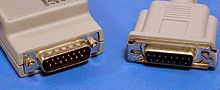
An AUI connector is a DA-15 (D-subminiature). It has a sliding clip in place of the thumbscrews normally found on a D-connector to hold two connectors together. This clip permits the MAU and MAC to be directly attached to one another even when their size and shape would preclude the use of thumbscrews. This clip is however frequently found to be awkward and/or unreliable.[by whom?]

| ||
|---|---|---|
| Pin | Signal | Description |
| 3 | DO-A | Data Out Circuit A |
| 10 | DO-B | Data Out Circuit B |
| 11 | DO-S | Data Out Circuit Shield (not used) |
| 5 | DI-A | Data In Circuit A |
| 12 | DI-B | Data In Circuit B |
| 4 | DI-S | Data In Circuit Shield |
| 7 | CO-A | Control Out Circuit A (not used) |
| 15 | CO-B | Control Out Circuit B (not used) |
| 8 | CO-S | Control Out Circuit Shield (not used) |
| 2 | CI-A | Control In Circuit A |
| 9 | CI-B | Control In Circuit B |
| 1 | CI-S | Control In Circuit Shield |
| 6 | VC | Voltage Common (0 V) |
| 13 | VP | Voltage Plus (+12 V) |
| 14 | VS | Voltage Shield (not used) |
| Shell | PG | Protective Ground |
See also[]
References[]
| Wikimedia Commons has media related to Attachment Unit Interface. |
- ^ "IEEE Standard for Ethernet, Section 1, Clause 7". IEEE Computer Society. Retrieved 14 February 2017.
- ^ IEEE 802.3 7. Physical Signaling (PLS) and Attachment Unit Interface (AUI) specifications
- ^ Overview of the XAUI, XLAUI and CAUI: Part1, "...the existing AUI was not suitable and it was replaced by the MII interface..."
- ^ Dan, Knight. "Apple's AAUI Ethernet Connector". Apple's AAUI Ethernet Connector. Retrieved 13 February 2012.
| hide Ethernet family of local area network technologies | |
|---|---|
| Speeds | |
| General | |
| Organizations | |
| Media | |
| Historic | |
| Applications | |
| Transceivers | |
| Interfaces | |
| |
- Ethernet
- Computer connectors