D-subminiature

The D-subminiature or D-sub is a common type of electrical connector. They are named for their characteristic D-shaped metal shield. When they were introduced, D-subs were among the smallest connectors used on computer systems.
Description, nomenclature, and variants[]


A D-sub contains two or more parallel rows of pins or sockets usually surrounded by a D-shaped metal shield that provides mechanical support, ensures correct orientation, and may screen against electromagnetic interference. D-sub connectors have gender: parts with pin contacts are called male connectors or plugs, while those with socket contacts are called female connectors or sockets. The socket's shield fits tightly inside the plug's shield. Panel mounted connectors usually have 4-40 jackscrews that accept screws on the cable end connector cover that are used for locking the connectors together and offering mechanical strain relief, and can be tightened with a 3/16" (or 5mm) hex socket. Occasionally the nuts may be found on a cable end connector if it is expected to connect to another cable end (see the male DE-9 pictured). When screened cables are used, the shields are connected to the overall screens of the cables. This creates an electrically continuous screen covering the whole cable and connector system.
The D-sub series of connectors was introduced by Cannon in 1952.[1] Cannon's part-numbering system uses D as the prefix for the whole series, followed by one of A, B, C, D, or E denoting the shell size, followed by the number of pins or sockets,[2] followed by either P (plug or pins[3]) or S (socket) denoting the gender of the part. Each shell size usually (see below for exceptions) corresponds to a certain number of pins or sockets: A with 15, B with 25, C with 37, D with 50, and E with 9.[4] For example, DB-25 denotes a D-sub with a 25-position shell size and a 25-position contact configuration. The contacts in each row of these connectors are spaced 326/3000 of an inch apart, or approximately 0.1087 inches (2.76 mm), and the rows are spaced 0.112 inches (2.84 mm) apart; the pins in the two rows are offset by half the distance between adjacent contacts in a row.[5] This spacing is called normal density. The suffixes M and F (for male and female) are sometimes used instead of the original P and S for plug and socket.
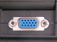
Later D-sub connectors added extra pins to the original shell sizes, and their names follow the same pattern. For example, the DE-15, usually found in VGA cables, has 15 pins in three rows, all surrounded by an E size shell. The pins are spaced at 0.090 inches (2.3 mm) horizontally and 0.078 inches (2.0 mm) vertically,[5] in what is called high density. The other connectors with the same pin spacing are the DA-26, DB-44, DC-62, DD-78 and DF-104. They all have three rows of pins, except the DD-78 which has four, and the DF-104 which has five rows in a new, larger shell.[6] The double density series of D-sub connectors features even denser arrangements and consists of the DE-19, DA-31, DB-52, DC-79, and DD-100. These each have three rows of pins, except the DD-100, which has four.
| Normal density | High density | Double density | |||
|---|---|---|---|---|---|
| Name | Pin layout | Name | Pin layout | Name | Pin layout |
| DA-15 | 8-7 | DA-26 | 9-9-8 | DA-31 | 10-11-10 |
| DB-25 | 13-12 | DB-44 | 15-15-14 | DB-52 | 17-18-17 |
| DC-37 | 19-18 | DC-62 | 21-21-20 | DC-79 | 26-27-26 |
| DD-50 | 17-16-17 | DD-78 | 20-19-20-19 | DD-100 | 26-25-24-25 |
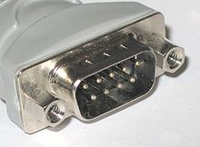
| DE-09 | 5-4 | DE-15 | 5-5-5 | DE-19 | 6-7-6 |
| 19-pin[shell sizes 1] | 10-9 | DF-104 | 21-21-21-21-20[6] | ||
| 23-pin[shell sizes 1] | 12-11 | ||||
| |||||
However, this naming pattern is not always followed. Because personal computers first used DB-25 connectors for their serial and parallel ports, when the PC serial port began to use 9-pin connectors, they were often labeled as DB-9 instead of DE-9 connectors, due to an ignorance of the fact that B represented a shell size. It is now common to see DE-9 connectors sold as DB-9 connectors. DB-9 nearly always refers to a 9-pin connector with an E size shell. The non-standard 23-pin D-sub connectors for external floppy drives and video output on most of the Amiga computers are usually labeled DB-23, even though their shell size is two pins smaller than ordinary DB sockets. Several computers also used a non-standard 19-pin D-sub connector, sometimes called DB-19,[7] including Macintosh (external floppy drive), Atari ST (external hard drive), and NeXT (Megapixel Display monitor[8] and laser printer).

Reflecting the same confusion of the letters DB with just D as mentioned above, high density connectors are also often called DB-15HD (or even DB-15 or HD-15), DB-26HD (HD-26), DB-44HD, DB-62HD, and DB-78HD connectors, respectively, where HD stands for high density.
Cannon also produced "combo" D-subs with larger contacts in place of some of the normal contacts, for use for high-current, high-voltage, or co-axial inserts. The DB-13W3 variant was commonly used for high-performance video connections; this variant provided 10 regular (#20) pins plus three coaxial contacts for the red, green, and blue video signals. Combo D-subs are currently manufactured in a broad range of configurations by other companies.[9] Some variants have current ratings up to 40 A; others are waterproof and meet IP67 standards.[citation needed]
A further family of connectors of similar appearance to the D-sub family uses names such as HD-50 and HD-68, and has a D-shaped shell about half the width of a DB25. They are common in SCSI attachments.
The original D-sub connectors are now defined by an international standard, IEC 60807-3 / DIN 41652. The United States military also maintains another specification for D-subminiature connectors, the MIL-DTL-24308 standard.[5]
Micro-D and Nano-D[]

Smaller connectors have been derived from the D-sub including the microminiature D (micro-D) and nanominiature D (nano-D) which are trademarks of ITT Cannon. Micro-D is about half the length of a D-sub and Nano-D is about half the length of Micro-D. Their primary applications are in military and space-grade technology. The MIL-SPEC for Micro-D is MIL-DTL-83513[10] and for Nano-D is MIL-DTL-32139.[11]
Typical applications[]

Communications ports[]
The widest application of D-subs is for RS-232 serial communications, though the standard did not make this connector mandatory. RS-232 devices originally used the DB25, but for many applications the less common signals were omitted, allowing a DE-9 to be used. The standard specifies a male connector for terminal equipment and a female connector for modems, but many variations exist. IBM PC-compatible computers tend to have male connectors at the device and female connectors at the modems. Early Apple Macintosh models used DE-9 connectors for RS-422 multi-drop serial interfaces (which can operate as RS-232). Later Macintosh models use 8-pin miniature DIN connectors instead.
On PCs, 25-pin and (beginning with the IBM PC/AT) 9-pin plugs were used for the RS-232 serial ports; 25-pin sockets were used for parallel ports (instead of the Centronics port found on the printer itself, which was inconveniently large for direct placement on the expansion cards).
Many uninterruptible power supply units have a DE-9F connector on them in order to signal to the attached computer via an RS-232 interface. Often these do not send data serially to the computer but instead use the handshaking control lines to indicate low battery, power failure, or other conditions. Such usage is not standardized between manufacturers and may require special cables.
Network ports[]
DE9 connectors were used for some Token Ring networks as well as other computer networks.

The Attachment Unit Interfaces that were used with 10BASE5 "thick net" in the 1980s and 1990s used DA15 connectors for connectivity between the Medium Attachment Units and (Ethernet) network interface cards, albeit with a sliding latch to lock the connectors together instead of the usual hex studs with threaded holes. The sliding latch was intended to be quicker to engage and disengage and to work in places where jackscrews could not be used for reasons of component shape.
DE-9 connectors are commonly used in Controller Area Network (CAN): female connectors are on the bus while male connectors are on devices.[12]
Computer video output[]
A female 9-pin connector on an IBM compatible personal computer may be a video display output such as MDA, Hercules, CGA, or EGA (rarely VGA or others). Even though these all use the same DE9 connector, the displays cannot all be interchanged and monitors or video interfaces may be damaged if connected to an incompatible device using the same connector.
Later analog video (VGA and later) adapters generally replaced these connectors with DE15 high-density sockets (though some early VGA devices still used DE9 connectors). DE15 connectors are similar to DE9 connectors (see above).
Many Apple Macintosh models, beginning with the Macintosh II, used DA15 sockets for analogue RGB video out. The earlier Apple IIgs used the same connector for the same purpose, but with an incompatible pinout. A digital (and thus also incompatible) RGB adapter for the Apple IIe also used a DA15F. The Apple IIc used a DA15F for an auxiliary video port which was not RGB, but provided the necessary signals to derive RGB.
Game controller ports[]

Starting in the late 1970s the Atari 2600 game console used modified DE9 connectors (male on the system, female on the cable) for its game controller connectors. The Atari joystick ports had bodies entirely of molded plastic without the metal shield, and they omitted the pair of fastening screws. In the years following, various video game consoles and home computers adopted the same connector for their own game ports, though they were not all interoperable. The most common wiring supported five digital connections (for up, down, left, and right movement, and one fire button), plus one pair of analog 100 kΩ potentiometers or paddles. Some computers supported additional buttons, and on some computers additional devices, such as a computer mouse, a light pen, or a graphics tablet were also supported via the game port. Unlike the basic one-button digital joysticks and the basic paddles, such devices were not typically interchangeable between different systems.
Systems utilizing the DE9 connector for their game port included the Texas Instruments TI-99/4A;[13] Atari 8-bit and ST lines; the Commodore VIC-20, 64, 128, and Amiga; the Amstrad CPC (which employed daisy-chaining when connecting two Amstrad-specific joysticks); the MSX, X68000, and FM Towns, predominantly used in Japan; the ColecoVision; the early Sega platforms (e.g. SG-1000, Master System and Mega Drive/Genesis); and the 3DO Interactive Multiplayer. The ZX Spectrum lacked a built-in joystick connector of any kind but aftermarket interfaces provided the ability to connect DE9 joysticks. NEC's home computers (e.g. PC-88, PC-98) also used DE9 connectors for game controllers, depending on the sound card used.
Many Apple II computers also used DE9 connectors for joysticks, but they had a female port on the computer and a male on the controller, used analog rather than digital sticks, and the pinout was completely unlike that used on the aforementioned systems. DE9 connectors were not used for game ports on the Apple Macintosh, Apple III, IBM PC systems, or most game consoles outside the aforementioned examples. Sega switched to proprietary controller ports for the Saturn and Dreamcast.
DA15S connectors are used for PC joystick connectors, where each DA15 connector supports two joysticks each with two analog axes and two buttons. In other words, one DA15S "game adapter" connector has 4 analog potentiometer inputs and 4 digital switch inputs. This interface is strictly input-only, though it does provide +5 V DC power. Some joysticks with more than two axes or more than two buttons use the signals designated for both joysticks. Conversely, Y-adapter cables are available that allow two separate joysticks to be connected to a single DA15 game adapter port; if a joystick connected to one of these Y-adapters has more than two axes or buttons, only the first two of each will work.
The IBM DA15 PC game connector has been modified to add a (usually MPU-401 compatible) MIDI interface, and this is often implemented in the game connectors on third-party sound cards, for example the Sound Blaster line from Creative Labs. The "standard" straight game adapter connector (introduced by IBM) has three ground pins and four +5 V power pins, and the MIDI adaptation replaces one of the grounds and one of the +5 V pins, both on the bottom row of pins, with MIDI In and MIDI Out signal pins. (There is no MIDI Thru provided.) Creative Labs introduced this adaptation.[citation needed]
The Neo Geo AES game console also used the DA15 connector, however, the pins are wired differently and it is therefore not compatible with the regular DA15 PC game controllers.
Other[]
25-pin sockets on Macintosh computers are typically single-ended SCSI connectors, combining all signal returns into one contact (again in contrast to the Centronics C50 connector typically found on the peripheral, supplying a separate return contact for each signal), while older Sun hardware uses DD50 connectors for Fast-SCSI equipment. As SCSI variants from Ultra2 onwards used differential signalling, the Macintosh DB25 SCSI interface became obsolete.
The complete range of D-sub connectors also includes DA15s (one row of 7 and one of 8), DC37s (one row of 18 and one of 19), and DD50s (two rows of 17 and one of 16); these are often used in industrial products, the 15-way version being commonly used on rotary and linear encoders.
The early Macintosh and late Apple II computers used an obscure 19-pin D-sub for connecting external floppy disk drives. Atari also used this connector on their 16-bit computer range for attaching hard disk drives and the Atari laser printer, where it was known as both the ACSI (Atari Computer System Interface) port and the DMA bus port. The Commodore Amiga used an equally unusual 23-pin version for both its video output (DB23M) and its port for daisy-chaining up to 3 extra external floppy disk drives (DB23F).
In professional audio, several connections use DB25 connectors:
- TASCAM and many others are using a connection over DB25 connectors,[14] which has been standardized into . This connection transports AES3 digital audio or analog audio using the same pinout.[15]
- TASCAM initially used their TDIF connection over DB25 connectors for their multi-track recording audio equipment. The transported signals are not AES3 compatible.
- Roland used DB25 connectors for their multi-track recording audio equipment (). A few patch panels have been made which have the DB25 connectors on the back with phone jacks (or even TRS phone connectors) on the front, however these are normally wired for TASCAM, which is more common outside of broadcasting.
In broadcast and professional video, "parallel digital" is a digital video interface that uses DB25 connectors, per the SMPTE 274M specification adopted in the late 1990s. The more common SMPTE 259M "serial digital interface" (SDI) uses BNC connectors for digital video signal transfer.
D-SUB 37 connectors are commonly used in Hospital facilities as an interface between hospital beds and nurse call systems, allowing for the connection and signaling of Nurse Call, Bed Exit, and Cord out including TV entertainment and lighting controls.
DB-25 connectors are commonly used to carry analog signals for beam displacement and color to laser projectors, as specified in the ISP-DB25 protocol published by the International Laser Display Association.[16]
Wire-contact attachment types[]


There are at least seven different methods used to attach wires to the contacts in D-sub connectors.
- Solder-bucket (or solder-cup) contacts have a cavity into which the stripped wire is inserted and hand-soldered.
- Insulation displacement contacts (IDCs) allow a ribbon cable to be forced onto sharp tines on the back of the contacts; this action pierces the insulation of all the wires simultaneously. This is a very quick means of assembly whether done by hand or machine.
- Crimp contacts are assembled by inserting a stripped wire end into a cavity in the rear of the contact, then crushing the cavity using a crimp tool, causing the cavity to grip the wire tightly at many points. The crimped contact is then inserted into the connector where it locks into place. Individual crimped pins can be removed later by inserting a special tool into the rear of the connector.
- PCB pins are soldered directly to a printed circuit board and not to a wire. Traditionally through hole plated (THP) board style pins were used (print) but increasingly gull-wing surface mount (SMD) connections are used, although the latter frequently exhibit solder pad contact problems when exposed to mechanical stress. These connectors are frequently mounted at a right angle to the PCB, allowing a cable to be plugged into the edge of the PCB assembly. While angled connectors traditionally occupied significant room on the PCB, flat SMD connector variants are produced by various manufacturers. Electrical/mechanical anchor points (often soldered) for the connector shell and locking screws are also provided but significantly differ in their position between US and EU connector variants, so that the correct type must be used unless the PCB was designed to accept them both. The PCB connectors are available in variants with either inch or metric pitch of the soldered contacts. Tolerances are typically large enough to allow the mounting of the smaller connectors regardless of the pitch variant used, but this does not hold true for the larger connectors.
- Wire wrap connections are made by wrapping solid wire around a square post with a wire wrap tool. This type of connection is often used in developing prototypes.
The wire wrap and IDC connections styles had to contend with incompatible pin spacing to the 0.05 in ribbon cable or 0.1 in proto board grid, especially for larger pin counts.
Usage[]
This section does not cite any sources. (October 2020) |
The 25-pin D-sub connector is still occasionally used in recording studios for multi-channel analog audio and AES digital audio.
The D-sub connector family is now out of general usage in the computer industry, due to size and cost. For portable devices such as PDAs, MP3 players, laptops, and smartphones, the D-sub connector is far too large to fit.
Because of their relative complexity (the D-shaped metal shield, the screws and nuts), D-sub connectors are inherently more expensive than later connectors that superseded them.
The physical design of D-sub connectors is ill-suited for consumer plug-and-play applications. Thin metal pins, especially in higher-density connectors, are easily bent or broken, particularly if frequently plugged in by touch behind equipment. The need to tighten screws for a secure connection is cumbersome. There is a high risk of shorting the male pins with the mating connector's surrounding lip as well. Although ESD- and EMI-resistant D-sub connectors exist, the fundamental design was never intended to protect from electrostatic discharge or electromagnetic interference or facilitate very high-frequency interconnections.
For video applications the DE15HD connector has been replaced by DVI, HDMI and DisplayPort connectors. A notable exception to this replacement is on the few analog CRT monitors still in use: the analog version of the DVI connector is similar in price and more complex than the D-sub, so the shift away from D-subs was slow in this case. For the majority of consumer applications, D-sub serial and parallel connectors have been replaced by the physically much simpler and cheaper IEEE 1394 (FireWire), SATA, USB, Thunderbolt or modular connectors. These connectors tend to be less rugged and durable than D-sub connectors—for example, the SATA connector as part of a cable assembly is specified to withstand only 50 manual insertions—but the robustness of the D-sub is more than is needed in many consumer product applications.
Due to the environments within factories and mills, serial and parallel protocols are commonly used (and in some cases current standards) for their combination of maximum cable length, sufficient speed, and compatibility with old equipment with long life expectancies. As D-Sub connectors have remained popular with these specifications, they are still commonly in use today where their robustness is required. The connectors' pricing is also less of a concern as most industrial equipment is limited in production with higher markup per unit and is generally expected to be supported by service contracts.
See also[]
- Centronics printer port (IEEE 1284)
- Game port
- Gender of connectors and fasteners
- Micro ribbon
- MMJ
- SCSI
References[]
- ^ "Are D Subs from all manufactures compatible?" (FAQ reply). ITT Cannon. Archived from the original on 2012-03-09.
- ^ Ishmael Stefanov-Wagner. "D-Subminiature Nomenclature". Archived from the original on January 11, 2009.
- ^ Silver, Ward (2011). The ARRL General Class License Manual For Ham Radio (Seventh ed.). The American Radio Relay League, Inc. p. 4-37. ISBN 978-0-87259-811-9.
- ^ ITT Cannon 90° PCB Selection Guide (PDF), RS Components, 2007-09-10
- ^ Jump up to: a b c "List Mil Specs", DSCC, DLA, archived from the original on 2013-02-21, retrieved 2010-08-18
- ^ Jump up to: a b "DF-104P D-subminiature connector pinout drawings". interfacebus.com. Retrieved 2014-07-24.
- ^ "DB-19 Substitute, Take Two". Big Mess o' Wires. 23 February 2016. Retrieved 2020-12-15.
- ^ Green, Chris; et al. (14 November 2009). "NeXTstation Teardown". iFixit. Retrieved 2020-12-17.
- ^ "Positronic Combo D-subminiature Connectors". FC Lane. Retrieved 1 July 2019.
- ^ "Connectors, Electrical, Rectangular, Microminiature, Polarized Shell, General Specification for (w/Amendment 5)". DEFENSE LOGISTICS AGENCY - DLA Land and Maritime - Mil Spec. Retrieved 2021-01-18.
- ^ "Connectors, Electrical, Rectangular, Nanominiature, Polarized Shell, General Specification for". DEFENSE LOGISTICS AGENCY - DLA Land and Maritime - Mil Spec. Retrieved 2021-01-18.
- ^ "CAN bus connector pinout". Interfacebus.com. Retrieved 2013-08-18.
- ^ Mace, Scott (1984-04-09). "Atarisoft vs. Commodore". InfoWorld. p. 50. Retrieved 4 February 2015.
- ^ "DTRS — Analog DB25 Pin-out" (PDF). Tascam. Retrieved 2010-08-18.
- ^ AES59-2012 Audio Engineering Society, Standard 59 — Audio application of 25-way D-type connectors in balanced circuits
- ^ "The ILDA Standard Projector" (PDF). International Laser Display Association. August 1999. Retrieved 2020-04-02.
External links[]
- "25 pin D‐sub male connector", Connector, RU: Pinouts, archived from the original on 2009-10-05, retrieved 2009-10-23. Comprehensive DB25 wiring diagrams: Tascam, Apple, SCSI, etc.
- Connector, RU: Pinouts. A list of common computer connectors, including most D-sub.
- "9 pin D‐sub female connector", Connector, RU: Pinouts, archived from the original on 2007-09-01, retrieved 2007-08-28. Devices with DE-9 connectors.
- DE-9 connector RS-232 pinout.
- Electrical connectors
- Electrical signal connectors
- Audiovisual connectors
- Computer connectors