Industrial computed tomography
Industrial computed tomography (CT) scanning is any computer-aided tomographic process, usually X-ray computed tomography, that uses irradiation to produce three-dimensional internal and external representations of a scanned object. Industrial CT scanning has been used in many areas of industry for internal inspection of components. Some of the key uses for industrial CT scanning have been flaw detection, failure analysis, metrology, assembly analysis and reverse engineering applications.[1][2] Just as in medical imaging, industrial imaging includes both nontomographic radiography (industrial radiography) and computed tomographic radiography (computed tomography).
Types of scanners[]

Line beam scanning is the traditional process of industrial CT scanning.[3] X-rays are produced and the beam is collimated to create a line. The X-ray line beam is then translated across the part and data is collected by the detector. The data is then reconstructed to create a 3-D volume rendering of the part.
In cone beam scanning, the part to be scanned is placed on a rotary table.[3] As the part rotates, the cone of X-rays produce a large number of 2D images that are collected by the detector. The 2D images are then processed to create a 3D volume rendering of the external and internal geometries of the part.

History[]
Industrial CT scanning technology was introduced in 1972 with the invention of the CT scanner for medical imaging by Godfrey Hounsfield. The invention earned him a Nobel Prize in medicine, which he shared with Allan McLeod Cormack.[4][5] Many advances in CT scanning have allowed for its use in the industrial field for metrology in addition to the visual inspection primarily used in the medical field (medical CT scan).
Analysis and inspection techniques[]
Various inspection uses and techniques include part-to-CAD comparisons, part-to-part comparisons, assembly and defect analysis, void analysis, wall thickness analysis, and generation of CAD data. The CAD data can be used for reverse engineering, geometric dimensioning and tolerance analysis, and production part approval.[6]
Assembly[]
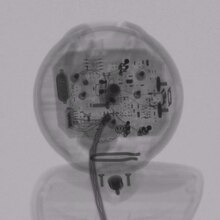
One of the most recognized forms of analysis using CT is for assembly, or visual analysis. CT scanning provides views inside components in their functioning position, without disassembly. Some software programs for industrial CT scanning allow for measurements to be taken from the CT dataset volume rendering. These measurements are useful for determining the clearances between assembled parts or the dimension of an individual feature.

Void, crack and defect detection[]
Traditionally, determining defects, voids and cracks within an object would require destructive testing. CT scanning can detect internal features and flaws displaying this information in 3D without destroying the part. Industrial CT scanning (3D X-ray) is used to detect flaws inside a part such as porosity,[7] an inclusion, or a crack.[8]
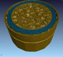
Metal casting and moulded plastic components are typically prone to porosity because of cooling processes, transitions between thick and thin walls, and material properties. Void analysis can be used to locate, measure, and analyze voids inside plastic or metal components.
Geometric dimensioning and tolerancing analysis[]
Traditionally, without destructive testing, full metrology has only been performed on the exterior dimensions of components, such as with a coordinate-measuring machine (CMM) or with a vision system to map exterior surfaces. Internal inspection methods would require using a 2D X-ray of the component or the use of destructive testing. Industrial CT scanning allows for full non-destructive metrology. With unlimited geometrical complexity, 3D printing allows for complex internal features to be created with no impact on cost, such features are not accessible using traditional CMM. The first 3D printed artefact that is optimised for characterisation of form using computed tomography CT [9]
Image-based finite element methods[]
Image-based finite element method converts the 3D image data from X-ray computed tomography directly into meshes for finite element analysis. Benefits of this method include modelling complex geometries (e.g. composite materials) or accurately modelling "as manufactured" components at the micro-scale.[10]
See also[]
References[]
- ^ Flisch, A., et al. Industrial Computer Tomography in Reverse Engineering Applications. DGZfP-Proceedings BB 67-CD Paper 8, Computerized Tomography for Industrial Applications and Image Processing in Radiology, March 15–17, 1999, Berlin, Germany.
- ^ Woods, Susan. "3-D CT inspection offers a full view of microparts", November 1, 2010.
- ^ a b Hofmann, J., Flisch, A., Obrist, A., Adaptive CT scanning-mesh based optimisation methods for industrial X-ray computer tomography applications. NDT&E International (37), 2004, pp. 271–278.
- ^ Zoofan, Bahman. "3D Micro-Tomography – A Powerful Engineering Tool". 3D Scanning Technologies. July 5, 2010.
- ^ Noel, Julien. "Advantages of CT in 3D Scanning of Industrial Parts. August 18, 2010.
- ^ "Reducing Preproduction Inspection Costs with Industrial (CT) Computed Tomography." Micro Manufacturing Magazine for the global micro manufacturing technology industry, August 2010.
- ^ Lambert, J.; Chambers, A. R.; Sinclair, I.; Spearing, S. M. (2012). "3D damage characterisation and the role of voids in the fatigue of wind turbine blade materials". Composites Science and Technology. 72 (2): 337. doi:10.1016/j.compscitech.2011.11.023.
- ^ Bull, D. J.; Helfen, L.; Sinclair, I.; Spearing, S. M.; Baumbach, T. (2013). "A comparison of multi-scale 3D X-ray tomographic inspection techniques for assessing carbon fibre composite impact damage" (PDF). Composites Science and Technology. 75: 55–61. doi:10.1016/j.compscitech.2012.12.006.
- ^ Shah, Paras; Racasan, Radu; Bills, Paul (2016-11-01). "Comparison of different additive manufacturing methods using computed tomography". Case Studies in Nondestructive Testing and Evaluation. 6: 69–78. doi:10.1016/j.csndt.2016.05.008. ISSN 2214-6571.
- ^ Evans, Ll. M.; Margetts, L.; Casalegno, V.; Lever, L. M.; Bushell, J.; Lowe, T.; Wallwork, A.; Young, P.; Lindemann, A. (2015-05-28). "Transient thermal finite element analysis of CFC–Cu ITER monoblock using X-ray tomography data". Fusion Engineering and Design. 100: 100–111. doi:10.1016/j.fusengdes.2015.04.048.
| X-ray/ Radiography |
| ||||||||||||
|---|---|---|---|---|---|---|---|---|---|---|---|---|---|
| MRI | |||||||||||||
| Ultrasound | |||||||||||||
| Radionuclide |
| ||||||||||||
| Optical/Laser | |||||||||||||
| Thermography | |||||||||||||
| Target conditions |
| ||||||||||||
| |||||||||||||
- Tomography
- Materials science
- Microscopes
- Microtechnology
- Nondestructive testing
- Reverse engineering