Shielded cable
This article needs additional citations for verification. (November 2008) |
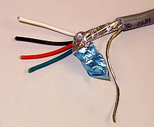


A shielded cable or screened cable is an electrical cable of one or more insulated conductors enclosed by a common conductive layer. The shield may be composed of braided strands of copper (or other metal, such as aluminium), a non-braided spiral winding of copper tape, or a layer of conducting polymer. Usually this shield is covered with a jacket.
The shield acts as a Faraday cage to reduce electrical noise from affecting the signals, and to reduce electromagnetic radiation that may interfere with other devices (see electromagnetic interference). The shield minimizes capacitively coupled noise from other electrical sources. The shield must be grounded to be effective.[1] The shield should be electrically continuous to maximize effectiveness, which includes cables splices.
In shielded signal cables the shield may act as the return path for the signal, or may act as screening only.
High voltage power cables with solid insulation are shielded to protect the cable insulation, people and equipment.
Coaxial cable is a type of shielded transmission line.
Types of Cable Shielding[]
This section needs expansion. You can help by . (October 2019) |
There are many types of cable shields available commercially, and usage depends on the application.
- Combination shields
- Foil Shields
- Metallic Braid Shields
- Spiral Shields
- Serve Shields
- Tape Shields
Signal cables[]
The best way to wire shielded cables for screening is to ground the shield at both ends of the cable.[2] Traditionally there existed a rule of thumb to ground only the source end of the shield to avoid ground loops. Best practice is to ground at both ends, but there is a possibility of ground loops. In airplanes, special cable is used with both an outer shield to protect against lightning and an inner shield grounded at one end to eliminate hum from the 400 Hz power system.[3]
Applications[]
The use of shielded cables in security systems provides some protection from power frequency and radio frequency interference, reducing the number of false alarms being generated. The best practice is to keep data or signal cables physically separated by at least 3 inches (75mm) from 'heavy' power circuits which are in parallel.
Analog signal cable used in professional audio applications is usually shielded twisted pair cable terminated in XLR connectors. The twisted pair carries the signal in a balanced audio configuration. The audio multicore cable laid from the stage to the mixing console is also shielded.
Consumers use screened copper wire with one central conductor in an unbalanced configuration.
Power cables[]
Medium and high-voltage power cables, in circuits over 2000 volts, usually have a shield layer of copper or aluminium tape or conducting polymer. If an unshielded insulated cable is in contact with earth or a grounded object, the electrostatic field around the conductor will be concentrated at the contact point, resulting in corona discharge, and eventual destruction of the insulation. Leakage current and capacitive current through the insulation presents a danger of electrical shock. The grounded shield equalizes electrical stress around the conductor, diverts any leakage current to ground. Stress relief cones should be applied at the shield ends, especially for cables operating at more than 2 kV to earth.
Shields on power cables may be connected to earth ground at each shield end and at splices for redundancy to prevent shock even though induced current will flow in the shield. This current will produce losses and heating and will reduce the maximum current rating of the circuit. Tests show that having a bare grounding conductor adjacent to the insulated wires will conduct the fault current to earth more quickly. On high-current circuits the shields might be connected only at one end. On very long high-voltage circuits, the shield may be broken into several sections since a long shield run may rise to dangerous voltages during a circuit fault. There is a risk of shock hazard from having only one end of the shield grounded. The maximum recommended shield potential rise is 25 volts.[citation needed] IEEE 422 and 525 lists the cable lengths that would limit shield potential to 25 volts for a single point ground application.[4][5][6]
| Size Conductor | One Cable per Duct (ft) | Three Cables per Duct (ft) |
|---|---|---|
| 1/0 AWG | 1250 | 4500 |
| 2/0 AWG | 1110 | 3970 |
| 4/0 AWG | 865 | 3000 |
| 250 kcmil | 815 | 2730 |
| 350 kcmil | 710 | 2260 |
| 400 kcmil | 655 | 2100 |
| 500 kcmil | 580 | 1870 |
| 750 kcmil | 510 | 1500 |
| 1000 kcmil | 450 | - |
| 2000 kcmil | 340 | - |
See also[]
References[]
- ^ "Shield Grounding". Retrieved 2019-02-28.
- ^ "Bonding Cable Shields at Both Ends to Avoid Noise".
- ^ "Aero 10 - Loop Resistance Tester". 090528 boeing.com
- ^ Thomas P. Arnold; C. David Mercier (1997). Southwire Company Power Cable Manual (2 ed.). Carrollton, GA 30119: Southwire Company.CS1 maint: location (link)
- ^ IEEE 422: IEEE Guide for the Design and Installation of Cable Systems in Power Generating Stations
- ^ IEEE 525: IEEE Guide for the Design and Installation of Cable Systems in Substations
- Signal cables