Telegraph code
A telegraph code is one of the character encodings used to transmit information by telegraphy. Morse code is the best-known such code. Telegraphy usually refers to the electrical telegraph, but telegraph systems using the optical telegraph were in use before that. A code consists of a number of code points, each corresponding to a letter of the alphabet, a numeral, or some other character. In codes intended for machines rather than humans, code points for control characters, such as carriage return, are required to control the operation of the mechanism. Each code point is made up of a number of elements arranged in a unique way for that character. There are usually two types of element (a binary code), but more element types were employed in some codes not intended for machines. For instance, American Morse code had about five elements, rather than the two (dot and dash) of International Morse Code.
Codes meant for human interpretation were designed so that the characters that occurred most often had the fewest elements in the corresponding code point. For instance, Morse code for E, the most common letter in English, is a single dot ( ▄ ), whereas Q is ▄▄▄ ▄▄▄ ▄ ▄▄▄ . These arrangements meant the message could be sent more quickly and it would take longer for the operator to become fatigued. Telegraphs were always operated by humans until late in the 19th century. When automated telegraph messages came in, codes with variable-length code points were inconvenient for machine design of the period. Instead, codes with a fixed length were used. The first of these was the Baudot code, a five-bit code. Baudot has only enough code points to print in upper case. Later codes had more bits (ASCII has seven) so that both upper and lower case could be printed. Beyond the telegraph age, modern computers require a very large number of code points (Unicode has 21 bits) so that multiple languages and alphabets (character sets) can be handled without having to change the character encoding. Modern computers can easily handle variable-length codes such as UTF-8 and UTF-16 which have now become ubiquitous.
Manual telegraph codes[]
Optical telegraph codes[]

Prior to the electrical telegraph, a widely used method of building national telegraph networks was the optical telegraph consisting of a chain of towers from which signals could be sent by semaphore or shutters from tower to tower. This was particularly highly developed in France and had its beginnings during the French Revolution. The code used in France was the Chappe code, named after Claude Chappe the inventor. The British Admiralty also used the semaphore telegraph, but with their own code. The British code was necessarily different from that used in France because the British optical telegraph worked in a different way. The Chappe system had moveable arms, as if it were waving flags as in flag semaphore. The British system used an array of shutters that could be opened or closed.[1]
Chappe code[]
The Chappe system consisted of a large pivoted beam (the regulator) with an arm at each end (the indicators) which pivoted around the regulator on one extremity. The angles these components were allowed to take was limited to multiples of 45° to aid readability. This gave a code space of 8×4×8 code points, but the indicator position inline with the regulator was never used because it was hard to distinguish from the indicator being folded back on top of the regulator, leaving a code space of 7×4×7 = 196. Symbols were always formed with the regulator on either the left- or right-leaning diagonal (oblique) and only accepted as valid when the regulator moved to either the vertical or horizontal position. The left oblique was always used for messages, with the right oblique being used for control of the system. This further reduced the code space to 98, of which either four or six code points (depending on version) were control characters, leaving a code space for text of 94 or 92 respectively.
The Chappe system mostly transmitted messages using a code book with a large number of set words and phrases. It was first used on an experimental chain of towers in 1793 and put into service from Paris to Lille in 1794. The code book used this early is not known for certain, but an unidentified code book in the Paris Postal Museum may have been for the Chappe system. The arrangement of this code in columns of 88 entries led Holzmann & Pehrson to suggest that 88 code points might have been used. However, the proposal in 1793 was for ten code points representing the numerals 0–9, and Bouchet says this system was still in use as late as 1800 (Holzmann & Pehrson put the change at 1795). The code book was revised and simplified in 1795 to speed up transmission. The code was in two divisions, the first division was 94 alphabetic and numeric characters plus some commonly used letter combinations. The second division was a code book of 94 pages with 94 entries on each page. A code point was assigned for each number up to 94. Thus, only two symbols needed to be sent to transmit an entire sentence – the page and line numbers of the code book, compared to four symbols using the ten-symbol code.
In 1799, three additional divisions were added. These had additional words and phrases, geographical places, and names of people. These three divisions required extra symbols to be added in front of the code symbol to identify the correct book. The code was revised again in 1809 and remained stable thereafter. In 1837 a horizontal only coding system was introduced by Gabriel Flocon which did not require the heavy regulator to be moved. Instead, an additional indicator was provided in the centre of the regulator to transmit that element of the code.[2]

Edelcrantz code[]

The Edelcrantz system was used in Sweden and was the second largest network built after that of France. The telegraph consisted of a set of ten shutters. Nine of these were arranged in a 3×3 matrix. Each column of shutters represented a binary-coded octal digit with a closed shutter representing "1" and the most significant digit at the bottom. Each symbol of telegraph transmission was thus a three-digit octal number. The tenth shutter was an extra-large one at the top. Its meaning was that the codepoint should be preceded by "A".
One use of the "A" shutter was that a numeral codepoint preceded by "A" meant add a zero (multiply by ten) to the digit. Larger numbers could be indicated by following the numeral with the code for hundreds (236), thousands (631) or a combination of these. This required fewer symbols to be transmitted than sending all the zero digits individually. However, the main purpose of the "A" codepoints was for a codebook of predetermined messages, much like the Chappe codebook.
The symbols without "A" were a large set of numerals, letters, common syllables and words to aid code compaction. Around 1809, Edelcrantz introduced a new codebook with 5,120 codepoints, each requiring a two-symbol transmission to identify.
| A | B | C | D | E | F | G | H | I | J | K | L | M | N | O | P | Q | R | S | T |
|---|---|---|---|---|---|---|---|---|---|---|---|---|---|---|---|---|---|---|---|
| 003 | 026 | ✗ | 055 | 112 | 125 | 162 | 210 | 254 | ✗ | 274 | 325 | 362 | 422 | 450 | 462 | ✗ | 500 | 530 | 610 |
| U | V | W | X | Y | Z | Å | Ä | Ö | 1 | 2 | 3 | 4 | 5 | 6 | 7 | 8 | 9 | 00 | 000 |
| 640 | 650 | ✗ | 710 | 711 | 712 | 713 | 723 | 737 | 001 | 002 | 004 | 010 | 020 | 040 | 100 | 200 | 400 | 236 | 631 |
There were many codepoints for error correction (272, error), flow control, and supervisory messages. Usually, messages were expected to be passed all the way down the line, but there were circumstances when individual stations needed to communicate directly, usually for managerial purposes. The most common, and simplest situation was communication between adjacent stations. Codepoints 722 and 227 was used for this purpose, to get the attention of the next station towards, or away from the sun respectively. For more remote stations codepoints 557 and 755 respectively were used, followed by the identification of the requesting and target stations.[3]
Wig-wag[]
Flag signalling was widely used for point-to-point signalling prior to the optical telegraph, but it was difficult to construct a nationwide network with hand-held flags. The much larger mechanical apparatus of the semaphore telegraph towers was needed so that a greater distance between links could be achieved. However, an extensive network with hand-held flags was constructed during the American Civil War. This was the wig-wag system which used the code invented by Albert J. Myer. Some of the towers used were enormous, up to 130 feet, to get a good range. Myer's code required only one flag using a ternary code. That is, each code element consisted of one of three distinct flag positions. However, the alphabetical codepoints required only two positions, the third position only being used in control characters. Using a ternary code in the alphabet would have resulted in shorter messages because fewer elements are required in each codepoint, but a binary system is easier to read at long distance since fewer flag positions need to be distinguished. Myer's manual also describes a ternary-coded alphabet with a fixed length of three elements for each codepoint.[4]
Electrical telegraph codes[]
Cooke and Wheatstone and other early codes[]
Many different codes were invented during the early development of the electrical telegraph. Virtually every inventor produced a different code to suit their particular apparatus. The earliest code used commercially on an electrical telegraph was the Cooke and Wheatstone telegraph five needle code (C&W5). This was first used on the Great Western Railway in 1838. C&W5 had the major advantage that the code did not need to be learned by the operator; the letters could be read directly off the display board. However, it had the disadvantage that it required too many wires. A one needle code, C&W1, was developed that required only one wire. C&W1 was widely used in the UK and the British Empire.

Some other countries used C&W1, but it never became an international standard and generally each country developed their own code. In the US, American Morse code was used, whose elements consisted of dots and dashes distinguished from each other by the length of the pulse of current on the telegraph line. This code was used on the telegraph invented by Samuel Morse and Alfred Vail and was first used commercially in 1844. Morse initially had code points only for numerals. He planned that numbers sent over the telegraph would be used as an index to a dictionary with a limited set of words. Vail invented an extended code that included code points for all the letters so that any desired word could be sent. It was Vail's code that became American Morse. In France, the telegraph used the Foy-Breguet telegraph, a two-needle telegraph that displayed the needles in Chappe code, the same code as the French optical telegraph, which was still more widely used than the electrical telegraph in France. To the French, this had the great advantage that they did not need to retrain their operators in a new code.[5]
Standardisation—Morse code[]

In Germany in 1848, Friedrich Clemens Gerke developed a heavily modified version of American Morse for use on German railways. American Morse had three different lengths of dashes and two different lengths of space between the dots and dashes in a code point. The Gerke code had only one length of dash and all inter-element spaces within a code point were equal. Gerke also created code points for the German umlaut letters, which do not exist in English. Many central European countries belonged to the German-Austrian Telegraph Union. In 1851, the Union decided to adopt a common code across all its countries so that messages could be sent between them without the need for operators to recode them at borders. The Gerke code was adopted for this purpose.
In 1865, a conference in Paris adopted the Gerke code as the international standard, calling it International Morse Code. With some very minor changes, this is the Morse code used today. The Cooke and Wheatstone telegraph needle instruments were capable of using Morse code since dots and dashes could be sent as left and right movements of the needle. By this time, the needle instruments were being made with end stops that made two distinctly different notes as the needle hit them. This enabled the operator to write the message without looking up at the needle which was much more efficient. This was a similar advantage to the Morse telegraph in which the operators could hear the message from the clicking of the relay armature. Nevertheless, after the British telegraph companies were nationalised in 1870 the General Post Office decided to standardise on the Morse telegraph and get rid of the many different systems they had inherited from private companies.
In the US, telegraph companies refused to use International Morse because of the cost of retraining operators. They opposed attempts by the government to make it law. In most other countries, the telegraph was state controlled so the change could simply be mandated. In the US, there was no single entity running the telegraph. Rather, it was a multiplicity of private companies. This resulted in international operators needing to be fluent in both versions of Morse and to recode both incoming and outgoing messages. The US continued to use American Morse on landlines (radiotelegraphy generally used International Morse) and this remained the case until the advent of teleprinters which required entirely different codes and rendered the issue moot.[6]
Transmission speed[]

The speed of sending in a manual telegraph is limited by the speed the operator can send each code element. Speeds are typically stated in words per minute. Words are not all the same length, so literally counting the words will get a different result depending on message content. Instead, a word is defined as five characters for the purpose of measuring speed, regardless of how many words are actually in the message. Morse code, and many other codes, also do not have the same length of code for each character of the word, again introducing a content-related variable. To overcome this, the speed of the operator repeatedly transmitting a standard word is used. PARIS is classically chosen as this standard because that is the length of an average word in Morse.[7]
In American Morse, the characters are generally shorter than International Morse. This is partly because American Morse uses more dot elements, and partly because the most common dash, the short dash, is shorter than the International Morse dash—two dot elements against three dot elements long. In principle, American Morse will be transmitted faster than International Morse if all other variables are equal. In practice, there are two things that detract from this. Firstly, American Morse, with around five coding elements was harder to get the timings right when sent quickly. Inexperienced operators were apt to send garbled messages, an effect known as hog Morse. The second reason is that American Morse is more prone to intersymbol interference (ISI) because of the larger density of closely spaced dots. This problem was particularly severe on submarine telegraph cables, making American Morse less suitable for international communications. The only solution an operator had immediately to hand to deal with ISI was to slow down the transmission speed.[8]
Language character encodings[]
Morse code for non-Latin alphabets, such as Cyrillic or Arabic script, is achieved by constructing a character encoding for the alphabet in question using the same, or nearly the same code points as used in the Latin alphabet. Syllabaries, such as Japanese katakana, are also handled this way (Wabun code). The alternative of adding more code points to Morse code for each new character would result in code transmissions being very long in some languages.[9]
Languages that use logograms are more difficult to handle due to the much larger number of characters required. The Chinese telegraph code uses a codebook of around 9,800 characters (7,000 when originally launched in 1871) which are each assigned a four-digit number. It is these numbers that are transmitted, so Chinese Morse code consists entirely of numerals. The numbers must be looked up at the receiving end making this a slow process, but in the era when telegraph was widely used, skilled Chinese telegraphers could recall many thousands of the common codes from memory. The Chinese telegraph code is still used by law enforcement because it is an unambiguous method of recording Chinese names in non-Chinese scripts.[10]
Automatic telegraph codes[]
Baudot code[]

Early printing telegraphs continued to use Morse code, but the operator no longer sent the dots and dashes directly with a single key. Instead they operated a piano keyboard with the characters to be sent marked on each key. The machine generated the appropriate Morse code point from the key press. An entirely new type of code was developed by Émile Baudot, patented in 1874. The Baudot code was a 5-bit binary code, with the bits sent serially. Having a fixed length code greatly simplified the machine design. The operator entered the code from a small 5-key piano keyboard, each key corresponding to one bit of the code. Like Morse, Baudot code was organised to minimise operator fatigue with the code points requiring the fewest key presses assigned to the most common letters.
Early printing telegraphs required mechanical synchronisation between the sending and receiving machine. The Hughes printing telegraph of 1855 achieved this by sending a Morse dash every revolution of the machine. A different solution was adopted in conjunction with the Baudot code. Start and stop bits were added to each character on transmission, which allowed asynchronous serial communication. This scheme of start and stop bits was followed on all the later major telegraph codes.[11]
Murray code[]
On busy telegraph lines, a variant of the Baudot code was used with punched paper tape. This was the Murray code, invented by Donald Murray in 1901. Instead of directly transmitting to the line, the keypresses of the operator punched holes in the tape. Each row of holes across the tape had five possible positions to punch, corresponding to the five bits of the Murray code. The tape was then run through a tape reader which generated the code and sent it down the telegraph line. The advantage of this system was that multiple messages could be sent to line very fast from one tape, making better use of the line than direct manual operation could.
Murray completely rearranged the character encoding to minimise wear on the machine since operator fatigue was no longer an issue. Thus, the character sets of the original Baudot and the Murray codes are not compatible. The five bits of the Baudot code are insufficient to represent all the letters, numerals, and punctuation required in a text message. Further, additional characters are required by printing telegraphs to better control the machine. Examples of these control characters are line feed and carriage return. Murray solved this problem by introducing shift codes. These codes instruct the receiving machine to change the character encoding to a different character set. Two shift codes were used in the Murray code; figure shift and letter shift. Another control character introduced by Murray was the delete character (DEL, code 11111) which punched out all five holes on the tape. Its intended purpose was to remove erroneous characters from the tape, but Murray also used multiple DELs to mark the boundary between messages. Having all the holes punched out made a perforation which was easy to tear into separate messages at the receiving end. A variant of the Baudot–Murray code became an international standard as International Telegraph Alphabet no. 2 (ITA 2) in 1924. The "2" in ITA 2 is because the original Baudot code became the basis for ITA 1. ITA 2 remained the standard telegraph code in use until the 1960s and was still in use in places well beyond then.[12]

Computer age[]
The teleprinter was invented in 1915. This is a printing telegraph with a typewriter-like keyboard on which the operator types the message. Nevertheless, telegrams continued to be sent in upper case only because there was not room for a lower case character set in Baudot–Murray or ITA 2 codes. This changed with the arrival of computers and the desire to interface computer-generated messages or word processor composed documents with the telegraph system. An immediate problem was the use of shift codes which caused a difficulty with computer storage of text. If a part of a message, or only one character, was retrieved, it was not possible to tell which encoding shift should be applied without searching back through the rest of the message for the last shift control. This led to the introduction of the 6-bit TeleTypeSetter (TTS) code. In TTS, the additional bit was used to store the shift state, thus obviating the need for shift characters. TTS was also of some benefit to teleprinters as well as computers. Corruption of a TTS transmitted letter code just resulted in one wrong letter being printed, which could probably be corrected by the receiving user. On the other hand, corruption of an ITA 2 shift character resulted in all the message from that point onwards being garbled until the next shift character was sent.[13]
ASCII[]
By the 1960s, improving teleprinter technology meant that longer codes were nowhere near as significant a factor in teleprinter costs as they once were. The computer users' wanted lowercase characters and additional punctuation and both teleprinter and computer manufacturers wished to get rid of ITA 2 and its shift codes. This led the American Standards Association to develop a 7-bit code, the American Standard Code for Information Interchange (ASCII). The final form of ASCII was published in 1964 and it rapidly became the standard teleprinter code. ASCII was the last major code developed explicitly with telegraphy equipment in mind. Telegraphy rapidly declined after this and was largely replaced by computer networks, especially the Internet in the 1990s.
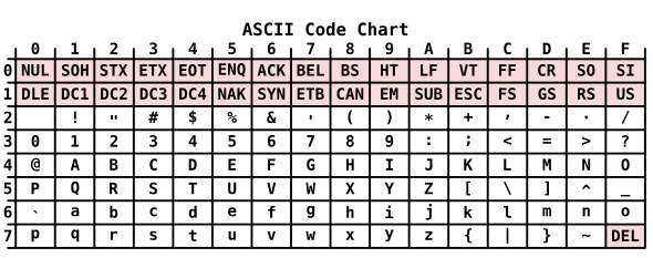
ASCII had several features geared to aid computer programming. The letter characters were in numerical order of code point, so an alphabetical sort could be achieved simply by sorting the data numerically. The code point for corresponding upper and lower case letters differed only by the value of bit 6, allowing a mix of cases to be sorted alphabetically if this bit was ignored. Other codes were introduced, notably IBM's EBCDIC derived from the punched card method of input, but it was ASCII and its derivatives that won out as the lingua franca of computer information exchange.[14]
ASCII extension and Unicode[]
The arrival of the microprocessor in the 1970s and the personal computer in the 1980s with their 8-bit architecture led to the 8-bit byte becoming the standard unit of computer storage. Packing 7-bit data into 8-bit storage is inconvenient for data retrieval. Instead, most computers stored one ASCII character per byte. This left one bit over that was not doing anything useful. Computer manufacturers used this bit in extended ASCII to overcome some of the limitations of standard ASCII. The main issue was that ASCII was geared to English, particularly American English, and lacked the accented vowels used in other European languages such as French. Currency symbols for other countries were also added to the character set. Unfortunately, different manufacturers implemented different extended ASCIIs making them incompatible across platforms. In 1987, the International Standards Organisation issued the standard ISO 8859-1, for an 8-bit character encoding based on 7-bit ASCII which was widely taken up.
ISO 8859 character encodings were developed for non-Latin scripts such as Cyrillic, Hebrew, Arabic, and Greek. This was still problematic if a document or data used more than one script. Multiple switches between character encodings was required. This was solved by the publication in 1991 of the standard for 16-bit Unicode, in development since 1987. Unicode maintained ASCII characters at the same code points for compatibility. As well as support for non-Latin scripts, Unicode provided code points for logograms such as Chinese characters and many specialist characters such as astrological and mathematical symbols. In 1996, Unicode 2.0 allowed code points greater than 16-bit; up to 20-bit, and 21-bit with an additional private use area. 20-bit Unicode provided support for extinct languages such as Old Italic script and many rarely used Chinese characters.[15]
International Code of Signals (radiotelegraph)[]
In 1931, the International Code of Signals, originally created for ship communication by signalling using flags, was expanded by adding a collection of five-letter codes to be used by radiotelegraph operators.
Comparison of codes[]
Comparison of flag codes[]
| Code | A N |
B O |
C P |
D Q |
E R |
F S |
G T |
H U |
I V |
J W |
K X |
L Y |
M Z |
Data type | Notes | Ref |
|---|---|---|---|---|---|---|---|---|---|---|---|---|---|---|---|---|
| Myer 2-element wig-wag | 11 22 |
1221 12 |
212 2121 |
111 2122 |
21 122 |
1112 121 |
1122 1 |
211 221 |
2 2111 |
2211 2212 |
1212 1211 |
112 222 |
2112 1111 |
Serial, variable length | 1=flag left, 2=flag right [note 1][note 2] |
[16] |
| International Morse in flag notation | 12 21 |
2111 222 |
2121 1221 |
211 2212 |
1 121 |
1121 111 |
221 2 |
1111 112 |
11 1112 |
1222 122 |
212 2112 |
1211 2122 |
22 2211 |
Serial, variable length | 1=flag left, 2=flag right | [17] |
| American Morse in flag notation | 12 21 |
2111 131 |
1131 11111 |
211 1121 |
1 1311 |
121 111 |
221 2 |
1111 112 |
11 1112 |
2121 122 |
212 1211 |
2+ 11311 |
22 11131 |
Serial, variable length | 1=flag left, 2=flag right, 3=flag dipped[note 3] | [18] |
| Myer 3-element wig-wag | 112 322 |
121 223 |
211 313 |
212 131 |
221 331 |
122 332 |
123 133 |
312 233 |
213 222 |
232 322 |
323 321 |
231 111 |
132 113 |
Serial, 3-element | 1=flag left, 2=flag right, 3=flag dipped | [19] |
Table 1 notes[]
- ^ Left and right are the message sender's left and right. The neutral position is with the flag raised above the signaller's head. Myer's manual specifies the code with the exact opposite movements (Myer (1872), p. 68), A is 22 for instance, but the oode actually used was commonly as shown here (Myer (1872), pp. 94–95).
- ^ The two element code actually had a third position defined. This was pointing the flag directly down at the ground. This element was only used in control characters. For instance, a single 3 meant "end of word", and 33 meant "end of sentence".
- ^ The "+" indicates a slight pause in that position.
Comparison of needle codes[]
| Code | A N |
B O |
C P |
D Q |
E R |
F S |
G T |
H U |
I V |
J W |
K X |
L Y |
M Z |
Data type | Notes | Ref |
|---|---|---|---|---|---|---|---|---|---|---|---|---|---|---|---|---|
| Schilling 1-needle (1820) |  |
Serial, variable length | This is the first code to use a single circuit. [note 1] |
[20] | ||||||||||||
| Gauss and Weber 1-needle (1833) |  |
Serial, variable length | [note 2] [note 1] |
[21] | ||||||||||||
| Cooke and Wheatstone 5-needle (1838) |  |
Parallel, 5-element | [note 3] | [22] | ||||||||||||
| Cooke and Wheatstone 2-needle |  |
Serial-parallel, variable length | [note 1] | [23] | ||||||||||||
| Cooke and Wheatstone 1-needle (1846) |  |
Serial, variable length | [note 4] [note 1] |
[24] | ||||||||||||
| Highton 1-needle |  |
Serial, variable length | [note 5] [note 1] |
[25] | ||||||||||||
| Morse as a needle code |  |
Serial, variable length | Needle left = dot Needle right = dash [note 6] |
[26] | ||||||||||||
| Foy-Breguet code (2-needle) |
 |
Parallel, 2-element | [note 7] | [27] | ||||||||||||
Table 2 notes[]
- ^ a b c d e On most needle telegraph codes, the short stroke is executed first on joined glyphs, regardless of whether it is to the left or right of the long stroke (Shaffner, p. 221). The Morse needle code is an exception; here all the strokes are executed in order (Hallas). If a short stroke does not dictate otherwise, the strokes are read left-to-right with one exception. The C&W 1-needle codes marked on the right of the faceplate (those codes where the long strokes are leaning right) are executed right-to-left, but still following short stroke first. Those on the left of the plate (left-leaning long strokes) are executed left-to-right as normal.
- ^ The Gauss and Weber code has shared codepoints for C/K, and there is no distinction of I/J. Burns shows V as having no code. Burns shows the code for D as \// which would make it the same as G, so probably an error, likewise Burns has \\// for Z. The codepoints for D and Z are as shown here in both Shiers and Calvert.
- ^ The C&W 5-needle codes for C, J, Q, V, X and Z were substituted with other letters.
- ^ The C&W 1-needle codes for J, Q and Z on early instruments were substituted with G, K and S respectively. The earlier table in this article shows these substitutes, this table shows the later unique codes. J remained missing from most instruments even after Q and Z were added. Most sources do not give a code for J; the tick symbol shown for it here is taken from the faceplate of the instrument pictured in the external links.
- ^ Some sources idnetify the Highton code as the Cooke and Wheatstone code (Guillemin for instance). This code is shown on the faceplate of Henry Highton's gold-leaf telegraph (Highton, p. 90) and his one-needle telegraph (Highton, p. 94). The latter instrument was used by Highton's British Electric Telegraph Company (Highton, p. 100). It was also used for a while by the Magnetic Telegraph Company who took them over (Morse, p. 116), and may have been used by a company closely associated with them, the Submarine Telegraph Company. Guillemin, writing in the context of Belgium who were connected to the UK via the Submarine Telegraph Company's Dover to Ostend cable, identifies this code as the "English code" (Gullemin, p. 551).
- ^ The tick marks used for Morse on needle telegraphs are read slightly differently to other codes. The short strokes are used to represent Morse dots, not to indicate which stroke is performed first. The strokes are read strict left-to-right. The time the needle is held to the right for a "dash" is usually the same as a left movement for a "dot" in contrast with a conventional Morse system using a sounder (Hallas).
- ^ The central bar in Foy-Breguet is fixed in position, the moveable needles are the two arms at the end of the bar.
An alternative representation of needle codes is to use the numeral "1" for needle left, and "3" for needle right. The numeral "2", which does not appear in most codes represents the needle in the neutral upright position. The codepoints using this scheme are marked on the face of some needle instruments, especially those used for training.[28]
Comparison of dot-dash codes[]
| Code | A N |
B O |
C P |
D Q |
E R |
F S |
G T |
H U |
I V |
J W |
K X |
L Y |
M Z |
Data type | Notes | Ref |
|---|---|---|---|---|---|---|---|---|---|---|---|---|---|---|---|---|
| Steinheil (1837) | ▄▄▄▄▄▄ ▄▄▄▄ |
▄▄▄▄▄▄▄▄ ▄▄▄▄▄▄ |
▄▄▄▄▄▄ ▄▄▄▄▄▄▄▄ |
▄▄▄▄ ✗ |
▄▄ ▄▄▄▄ |
▄▄▄▄▄▄ ▄▄▄▄▄▄▄▄ |
▄▄▄▄▄▄ ▄▄▄▄ |
▄▄▄▄▄▄▄▄ ▄▄▄▄▄▄ |
▄▄ ▄▄▄▄▄▄ |
▄▄ ▄▄▄▄▄▄▄▄ |
▄▄▄▄▄▄ ✗ |
▄▄▄▄▄▄ ✗ |
▄▄▄▄▄▄ ▄▄▄▄▄▄▄▄ |
Serial, variable length | [note 1] | [29] |
| Steinheil (1849) | ▄▄▄ ▄ ▄▄▄ ▄ ▄ |
▄▄▄ ▄ ▄ ▄▄▄ ▄▄▄ ▄▄▄ ▄▄▄ |
▄▄▄ ▄▄▄ ▄ ▄ ▄▄▄ ▄▄▄ ▄ |
▄▄▄ ▄ ▄▄▄ ▄▄▄ ▄ |
▄▄▄ ▄▄▄ ▄▄▄ |
▄▄▄ ▄ ▄ ▄▄▄ ▄▄▄ ▄ ▄ |
▄ ▄ ▄▄▄ ▄▄▄ ▄ |
▄ ▄▄▄ ▄ ▄▄▄ ▄ |
▄ ▄▄▄ ▄ ▄ |
▄ ▄ ▄▄▄ ▄ ▄▄▄ |
▄▄▄ ▄▄▄ ▄ ✗ |
▄ ▄▄▄ ▄▄▄ ✗ |
▄ ▄ ▄ ▄ ▄ ▄▄▄ ▄▄▄ |
Serial, variable length | [note 2] | [30] |
| Bain (1843) | ▄ ▄▄▄ ▄ ▄ ▄▄▄ ▄▄▄ |
▄ ▄▄▄ ▄ ▄▄▄ |
▄ ▄ ▄ ▄▄▄ ▄ ▄▄▄ |
▄ ▄ ▄▄▄ ▄▄▄ ▄ ▄▄▄ ▄ |
▄ ▄▄▄ ▄▄▄ ▄ |
▄ ▄▄▄ ▄▄▄ ▄▄▄ ▄▄▄ ▄ ▄ |
▄ ▄▄▄ ▄ ▄ ▄▄▄ ▄ ▄ ▄ |
▄ ▄▄▄ ▄▄▄ ▄▄▄ ▄ |
▄ ▄ ▄▄▄ ▄▄▄ ▄▄▄ ▄ |
▄ ▄ ▄ ▄▄▄ ▄▄▄ ▄▄▄ ▄ ▄ |
▄ ▄▄▄ ▄▄▄ ▄ ▄▄▄ ▄ ▄ ▄▄▄ |
▄ ▄ ▄ ▄ ▄▄▄ ▄▄▄ |
▄ ▄▄▄ ▄ ▄▄▄ ▄▄▄ ▄▄▄ ▄▄▄ |
Serial, variable length | [note 3] | [31] |
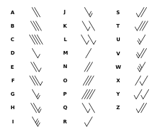
| Morse (c. 1838) | ▄ ▄ ▄ ▄▄▄ ▄ |
▄ ▄ ▄ ▄ ▄ ▄ |
▄ ▄ ▄ ▄ ▄ ▄ ▄ ▄ |
▄ ▄ ▄ ▄ ▄ ▄ ▄▄▄ ▄ |
▄ ▄ ▄ |
▄ ▄ ▄ ▄ ▄ ▄▄▄ ▄ |
▄ ▄ ▄ ▄▄▄ ▄▄▄ ▄ |
▄ ▄ ▄ ▄ ▄ ▄▄▄ ▄▄▄ |
▄ ▄▄▄ ▄▄▄ |
▄ ▄ ▄ ▄ ▄ ▄▄▄ |
▄▄▄ ▄ ▄▄▄ ▄▄▄ ▄▄▄ |
▄▄▄▄ ▄ ▄▄▄ |
▄▄▄ ▄ ▄ ▄ ▄▄▄ ▄ |
Serial, variable length | [note 4] | [32] |
| Morse (c. 1840) (American Morse) |
▄ ▄▄▄ ▄▄▄ ▄ |
▄▄▄ ▄ ▄ ▄ ▄ ▄ |
▄ ▄ ▄ ▄ ▄ ▄ ▄ ▄ |
▄▄▄ ▄ ▄ ▄ ▄ ▄▄▄ ▄ |
▄ ▄ ▄ ▄ |
▄ ▄▄▄ ▄ ▄ ▄ ▄ |
▄▄▄ ▄▄▄ ▄ ▄▄▄ |
▄ ▄ ▄ ▄ ▄ ▄ ▄▄▄ |
▄ ▄ ▄ ▄ ▄ ▄▄▄ |
▄▄▄ ▄ ▄▄▄ ▄ ▄ ▄▄▄ ▄▄▄ |
▄▄▄ ▄ ▄▄▄ ▄ ▄▄▄ ▄ ▄ |
▄▄▄▄ ▄ ▄ ▄ ▄ |
▄▄▄ ▄▄▄ ▄ ▄ ▄ ▄ |
Serial, variable length | [note 5] | [33] |
| Gerke (1848) (continental morse) |
▄ ▄▄▄ ▄▄▄ ▄ |
▄▄▄ ▄ ▄ ▄ ▄ ▄▄▄ ▄ ▄ ▄ |
▄▄▄ ▄ ▄▄▄ ▄ ▄ ▄ ▄ ▄ ▄ |
▄▄▄ ▄ ▄ ▄▄▄ ▄▄▄ ▄ ▄▄▄ |
▄ ▄ ▄▄▄ ▄ |
▄ ▄ ▄▄▄ ▄ ▄ ▄ ▄ |
▄▄▄ ▄▄▄ ▄ ▄▄▄ |
▄ ▄ ▄ ▄ ▄ ▄ ▄▄▄ |
▄ ▄ ▄ ▄ ▄ ▄▄▄ |
▄ ▄ ▄ ▄▄▄ ▄▄▄ |
▄▄▄ ▄ ▄▄▄ ▄ ▄ ▄▄▄ ▄ ▄ ▄ |
▄ ▄▄▄ ▄ ▄ ▄▄▄ ▄▄▄ ▄ ▄ ▄ |
▄▄▄ ▄▄▄ ▄ ▄▄▄ ▄▄▄ ▄ ▄ |
Serial, variable length | [note 6] | [34] |
| International Morse (1851) |
▄ ▄▄▄ ▄▄▄ ▄ |
▄▄▄ ▄ ▄ ▄ ▄▄▄ ▄▄▄ ▄▄▄ |
▄▄▄ ▄ ▄▄▄ ▄ ▄ ▄▄▄ ▄▄▄ ▄ |
▄▄▄ ▄ ▄ ▄▄▄ ▄▄▄ ▄ ▄▄▄ |
▄ ▄ ▄▄▄ ▄ |
▄ ▄ ▄▄▄ ▄ ▄ ▄ ▄ |
▄▄▄ ▄▄▄ ▄ ▄▄▄ |
▄ ▄ ▄ ▄ ▄ ▄ ▄▄▄ |
▄ ▄ ▄ ▄ ▄ ▄▄▄ |
▄ ▄▄▄ ▄▄▄ ▄▄▄ ▄ ▄▄▄ ▄▄▄ |
▄▄▄ ▄ ▄▄▄ ▄▄▄ ▄ ▄ ▄▄▄ |
▄ ▄▄▄ ▄ ▄ ▄▄▄ ▄ ▄▄▄ ▄▄▄ |
▄▄▄ ▄▄▄ ▄▄▄ ▄▄▄ ▄ ▄ |
Serial, variable length | [35] |
Table 3 notes[]
- ^ The 1837 Steinheil code has shared codepoints for C/K, and U/V. There is no distinction made between I and J. This code is almost identical to the 1849 code, except that it is designed for printing from pulses of negative and positive polarity rather than pulses of short and long duration.
- ^ The 1849 Steinheil code has shared codepoints for C/K/Q, D/T, and F/V (Gerke, p. 128). There is no distinction between I and J.
- ^ Bain's code is as given in Myer. Burns has several variant codepoints. Many of these are probably errors as they lead to duplicate codepoints, and Myer had worked as a telegraph operator on the Bain telegraph. Nevertheless, the differences are given here for completeness. Burns has ▄▄▄ ▄ for A, ▄ ▄▄▄ ▄▄▄ ▄ for Q, and ▄▄▄ ▄ ▄▄▄ ▄▄▄ for T. The codes for I and O are swapped.
- ^ The 1838 Morse code has shared codepoints for I/Y, G/J, and S/Z (Shiers, p. 102).
- ^ American Morse used a shorter dash than later codes (two dot units compared to three in International Morse). This is not reflected in the table for ease of comparison
- ^ The Gerke code did not distinguish between I and J. Both Burns and Gerke himself list only J. Huurdeman gives the International Morse codepoint for J. Burns has ▄ ▄ ▄▄▄ ▄ ▄ as the codepoint for X. This appears to be an error, both Huurdeman and Gerke have ▄ ▄ ▄▄▄ ▄ ▄ ▄ .
When used with a printing telegraph or siphon recorder, the "dashes" of dot-dash codes are often made the same length as the "dot". Typically, the mark on the tape for a dot is made above the mark for a dash. An example of this can be seen in the 1837 Steinheil code, which is nearly identical to the 1849 Steinheil code, except that they are represented differently in the table. International Morse code was commonly used in this form on submarine telegraph cables.[36]
Comparison of binary codes[]
| Code | A N |
B O |
C P |
D Q |
E R |
F S |
G T |
H U |
I V |
J W |
K X |
L Y |
M Z |
Data type | Notes | Ref |
|---|---|---|---|---|---|---|---|---|---|---|---|---|---|---|---|---|
| Baudot and ITA 1 | 01 1E |
0C 07 |
0D 1F |
0F 1D |
02 1C |
0E 14 |
0A 15 |
0B 05 |
06 17 |
09 16 |
19 12 |
1B 04 |
1A 13 |
Serial, 5-bit | [37] | |
| Baudot–Murray and ITA 2 | 03 0C |
19 18 |
0E 16 |
09 17 |
01 0A |
0D 05 |
1A 10 |
14 07 |
06 1E |
0B 13 |
0F 1D |
12 15 |
1C 11 |
Serial, 5-bit | [38] | |
| ASCII | 41/61 4E/6E |
42/62 4F/6F |
43/63 50/70 |
44/64 51/71 |
45/65 52/72 |
46/66 53/73 |
47/67 54/74 |
48/78 55/75 |
49/69 56/76 |
4A/6A 57/77 |
4B/6B 58/78 |
4C/6C 59/79 |
4D/6D 5A/7A |
Serial, 7-bit | [note 2] | [39] |
Table 4 notes[]
- ^ All codepoints in this table are given in hexadecimal for conciseness. Typically, they were actually transmitted as binary codes in asynchronous serial communication with binary "0" represented by a "space" (typically, a positive voltage) and "1" represented by a "mark" (typically, a negative voltage). Each transmitted character was preceded by a "start" symbol and finished with a "stop" symbol to maintain synchronisation (Toncich, p. 108).
- ^ Two codepoints are given in ASCII for each character. These represent, respectively, the uppercase and lowercase characters.
See also[]
- Commercial code (communications)
- Great Western Railway telegraphic codes
References[]
- ^ Beauchamp, ch. 1
- Bouchet, ch. 2
- Burns, ch. 2
- ^ Bouchet, ch. 2
- Coe, ch. 1
- Holzmann & Pehrson, ch. 2
- Shaffner, ch. 3
- ^ Holzmann & Pehrson, ch. 3
- Edelcrantz, ch. 4
- ^ Coe, ch. 1
- Myer (1866)
- Wrixon, ch. 11
- ^ Beauchamp, ch. 2
- Burns, ch. 3
- Chesnoy ch. 2
- Coe, ch. 2
- Guillemin, bk. 5, ch. 3
- Wrixon, ch. 10, 11
- ^ Beauchamp, ch. 3
- Chesnoy, ch. 2, pt. A
- Coe, ch. 3
- Guillemin, bk. 5, ch. 4
- Huurdeman, ch. 8.10
- Kieve, ch. 9
- Lyall, ch. 2
- ^ Coe, Appendixes
- ^ Coe, ch. 6
- ^ Gollings, ch. 6
- King, appx. A
- ^ Gollings, ch. 6
- Mullaney, ch. 7
- ^ Beauchamp, ch. 11
- Raykoff, ch. 8
- Noll, ch. 2
- ^ Huurdeman, ch. 19
- ^ Beauchamp, ch. 11
- Gillam, ch. 2
- ^ Gillam, ch. 2
- Huurdeman, ch. 30
- Noll, ch. 2
- ^ Gillam, ch. 2
- Gollings, ch. 6
- ^ Coe, p. 3
- Myer (1866), pp. 53, 80
- ^ Maver, pp. 363–364
- ^ Johnson, p. 525
- Maver, pp. 363–365
- ^ Myer (1866), p. 81
- ^ Shiers, pp. 101–102
- Calvert
- Shaffner, p. 137
- ^ Shiers, p. 101
- Burns, p. 76
- Calvert
- ^ Shaffner, pp. 200–201
- Burns, p. 76
- ^ Shaffner, pp. 226–229
- Guillemin, p. 554
- ^ Shaffner, p. 221
- Guillemin, p. 551
- Huurdeman, p. 68
- ^ Highton, p. 94
- Guillemin, p. 551
- ^ Hallas
- ^ Guillemin, p. 558
- ^ Highton, pp. 90–95
- Guillemin, pp. 550–551
- ^ Burns, p. 77
- Calvert
- ^ Burns, p. 77
- Gerke, p. 126
- ^ Myer (1851), p. 11
- Burns, p. 77
- ^ Shiers, pp. 101–103
- ^ Burns, p. 77
- Huurdeman, p. 144
- ^ Burns, p. 77
- Huurdeman, p. 144
- Gerke, p. 126
- ^ Gollings, p. 80
- Huurdeman, p. 144
- Burns, p. 77
- ^ Bright, pp. 601–606
- ^ Salomon, p. 21
- ^ Gollings, p. 83
- ^ Wyatt, pp. 681–684
Bibliography[]
- Beauchamp, Ken, History of Telegraphy, IET, 2001 ISBN 0852967926.
- Bouchet, Olivier, Wireless Optical Communications, Wiley, 2012 ISBN 1848213166.
- Bright, Charles Tilston, Submarine Telegraphs, London: Crosby Lockwood, 1898 OCLC 776529627.
- Burns, Russel W., Communications: An International History of the Formative Years, IEE, 2004 ISBN 0863413277.
- Calvert, James B., "The Electromagnetic Telegraph", accessed and archived 13 October 2019.
- Chesnoy, Jose, Undersea Fiber Communication Systems, Academic Press, 2002 ISBN 0-08-049237-1.
- Coe, Lewis, The Telegraph: A History of Morse's Invention and Its Predecessors in the United States, McFarland, 2003 ISBN 0-7864-1808-7.
- Edelcrantz, Abraham Niclas, Afhandling om Telegrapher ("A Treatise on Telegraphs"), 1796, as translated in ch. 4 of Holzmann & Pehrson.
- Gerke, Friedrich Clemens, Der praktische Telegraphist, oder, Die electro-magnetische Telegraphie, Hoffmann und Campe, 1851 OCLC 162961437.
- Gillam, Richard, Unicode Demystified, Addison-Wesley Professional, 2003 ISBN 0201700522.
- Gollings, Gus, "Multilingual Script Encoding", ch. 6 in, Cope, Bill; Gollings, Gus, Multilingual Book Production, Common Ground, 2001 ISBN 186335073X.
- Guillemin, Amédée, The Applications of Physical Forces, Macmillan and Company, 1877 OCLC 5894380237.
- Hallas, Stuart, M., "The Single Needle Telegraph", accessed and archived 5 October 2019.
- Highton, Edward, The Electric Telegraph: Its History and Progress, J. Weale, 1852 OCLC 999489281.
- Holzmann, Gerard J.; Pehrson, Björn, The Early History of Data Networks, Wiley, 1995 ISBN 0818667826.
- Huurdeman, Anton A., The Worldwide History of Telecommunications, John Wiley & Sons, 2003 ISBN 0471205052.
- Johnson, Rossiter (ed), Universal Cyclopædia and Atlas, vol. 10, D. Appleton and Company, 1901 LCCN 05-9702.
- Kieve, Jeffrey L., The Electric Telegraph: A Social and Economic History, David and Charles, 1973 OCLC 655205099.
- King, Thomas W., Modern Morse Code in Rehabilitation and Education, Allyn and Bacon, 2000 ISBN 0205287514.
- Lyall, Francis, International Communications: The International Telecommunication Union and the Universal Postal Union, Routledge, 2016 ISBN 1-317-114345.
- Maver, William, Jr., American Telegraphy and Encyclopedia of the Telegraph, Maver Publishing Company, 1909 OCLC 499312411.
- Mullaney, Thomas S., "Semiotic Sovereignty: The 1871 Chinese Telegraph Code in Historical Perspective", pp. 153–184 in, Jing Tsu; Elman, Benjamin A. (eds), Science and Technology in Modern China, 1880s–1940s, BRILL, 2014 ISBN 9004268782.
- Myer, Albert J., A New Sign Language for Deaf Mutes, Jewett, Thomas & Co., 1851 OCLC 1000370390.
- Myer, Albert J., A Manual of Signals, D. van Nostrand, 1866 OCLC 563202260.
- Myer, Albert J., A Manual of Signals, D. van Nostrand, 1872 OCLC 682033474.
- Noll, A. Michael, The Evolution of Media, Rowman & Littlefield, 2007 ISBN 0742554821.
- Raykoff, Ivan, "Piano, telegraph, typewriter: Listening to the language of touch", ch. 8 in, Colligan, Colette (ed); Linley, Margaret (ed), Media, Technology, and Literature in the Nineteenth Century, Routledge, 2016 ISBN 131709865X.
- Salomon, David, Data Compression: The Complete Reference, Springer Science & Business Media, 2007 ISBN 1846286034.
- Shaffner, Taliaferro Preston, The Telegraph Manual, Pudney & Russell, 1859 OCLC 258508686.
- Shiers, George, The Electric Telegraph: An Historical Anthology, Arno Press, 1977 OCLC 838764933, including reprints of parts of,
- Smithsonian Institution, Annual Report of the Board of Regents of the Smithsonian Institution, 1878, Smithsonian Institution, 1879 OCLC 1053068855.
- Toncich, Dario J., Data Communications and Networking for Manufacturing Industries, Chrystobel Engineering, 1993 ISBN 0646105221.
- Wrixon, Fred B., Codes, Ciphers, Secrets and Cryptic Communication, Black Dog & Leventhal Publishers, 2005 ISBN 1579124852.
- Wyatt, Allen L., Using Assembly Language, Que Corporation, 1887 ISBN 0880222972.
External links[]
- Single-needle telegraph instrument with Cooke and Wheatstone code marked on the dial and two-note endstops
- Cooke and Wheatstone style single-needle instrument with Morse code marked on the dial
- James B. Calvert, The Electromagnetic Telegraph, shows several encodings including Schilling (1820), Gauss and Weber (1833), Steinheil (1837), C&W1 (1846), C&W2 (1843), Bregeut (1844), Russian Morse, and a comparison chart of Morse type codes including the Bain code.
Character encodings | |
|---|---|
| Early telecommunications |
|
| ISO/IEC 8859 |
|
| Bibliographic use | |
| National standards | |
| ISO/IEC 2022 |
|
| Mac OS code pages ("scripts") |
|
| DOS code pages |
|
| IBM AIX code pages | |
| IBM code pages for other vendors' encodings | |
| Windows code pages |
|
| Microsoft code pages for other vendors' encodings | |
| EBCDIC code pages |
|
| DEC terminals (VTx) |
|
| Platform specific |
|
| Unicode / ISO/IEC 10646 |
|
| TeX typesetting system | |
| Miscellaneous code pages |
|
| Control and nonprinting character sets |
|
| Related topics |
|
- Telegraphy