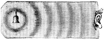
Isotropic radiator
This article needs additional citations for verification. (February 2013) |


An isotropic radiator is a theoretical point source of electromagnetic or sound waves which radiates the same intensity of radiation in all directions. It has no preferred direction of radiation. It radiates uniformly in all directions over a sphere centred on the source. Isotropic radiators are used as reference radiators with which other sources are compared, for example in determining the gain of antennas. A coherent isotropic radiator of electromagnetic waves is theoretically impossible, but incoherent radiators can be built. An isotropic sound radiator is possible because sound is a longitudinal wave.
The unrelated term isotropic radiation refers to radiation which has the same intensity in all directions, thus an isotropic radiator does not radiate isotropic radiation.
Physics[]
This section needs additional citations for verification. (September 2017) |
In physics, an isotropic radiator is a point radiation or sound source. At a distance, the sun is an isotropic radiator of electromagnetic radiation.
Antenna theory[]
In antenna theory, an isotropic antenna is a hypothetical antenna radiating the same intensity of radio waves in all directions. It thus is said to have a directivity of 0 dBi (dB relative to isotropic) in all directions.
In reality, a coherent isotropic radiator of linear polarization can be shown to be impossible. Its radiation field could not be consistent with the Helmholtz wave equation (derived from Maxwell's equations) in all directions simultaneously. Consider a large sphere surrounding the hypothetical point source, in the far field of the radiation pattern so that at that radius the wave over a reasonable area is essentially planar. In the far field the electric (and magnetic) field of a plane wave in free space is always perpendicular to the direction of propagation of the wave. So the electric field would have to be tangent to the surface of the sphere everywhere, and continuous along that surface. However the hairy ball theorem shows that a continuous vector field tangent to the surface of a sphere must fall to zero at one or more points on the sphere, which is inconsistent with the assumption of an isotropic radiator with linear polarization.
Incoherent isotropic radiators are possible and do not violate Maxwell's equations.[citation needed] Acoustic isotropic radiators are possible because sound waves in a gas or liquid are longitudinal waves and not transverse waves.
Even though an isotropic antenna cannot exist in practice, it is used as a base of comparison to calculate the directivity of actual antennas. Antenna gain , which is equal to the antenna's directivity multiplied by the antenna efficiency, is defined as the ratio of the intensity (power per unit area) of the radio power received at a given distance from the antenna (in the direction of maximum radiation) to the intensity received from a perfect lossless isotropic antenna at the same distance. This is called isotropic gain
Gain is often expressed in logarithmic units called decibels (dB). When gain is calculated with respect to an isotropic antenna, these are called decibels isotropic (dBi)
The gain of any perfectly efficient antenna averaged over all directions is unity, or 0 dBi.
Isotropic receiver[]
In EMF measurement applications, an isotropic receiver (also called isotropic antenna) is a calibrated radio receiver with an antenna which approximates an isotropic reception pattern; that is, it has close to equal sensitivity to radio waves from any direction. It is used as a field measurement instrument to measure electromagnetic sources and calibrate antennas. The isotropic receiving antenna is usually approximated by three orthogonal antennas or sensing devices with a radiation pattern of the omnidirectional type , such as short dipoles or small loop antennas.
The parameter used to define accuracy in the measurements is called isotropic deviation.
Optics[]
In optics, an isotropic radiator is a point source of light. The sun approximates an isotropic radiator of light. Certain munitions such as flares and chaff have isotropic radiator properties. Whether a radiator is isotropic is independent of whether it obeys Lambert's law. As radiators, a spherical black body is both, a flat black body is Lambertian but not isotropic, a flat chrome sheet is neither, and by symmetry the Sun is isotropic, but not Lambertian on account of limb darkening.
Sound[]
An isotropic sound radiator is a theoretical loudspeaker radiating equal sound volume in all directions. Since sound waves are longitudinal waves, a coherent isotropic sound radiator is feasible; an example is a pulsing spherical membrane or diaphragm, whose surface expands and contracts radially with time, pushing on the air.[1]
Derivation of aperture of an isotropic antenna[]

The aperture of an isotropic antenna can be derived by a thermodynamic argument.[2][3][4] Suppose an ideal (lossless) isotropic antenna A located within a thermal cavity CA, is connected via a lossless transmission line through a band-pass filter Fν to a matched resistor R in another thermal cavity CR (the characteristic impedance of the antenna, line and filter are all matched). Both cavities are at the same temperature . The filter Fν only allows through a narrow band of frequencies from to . Both cavities are filled with blackbody radiation in equilibrium with the antenna and resistor. Some of this radiation is received by the antenna. The amount of this power within the band of frequencies passes through the transmission line and filter Fν and is dissipated as heat in the resistor. The rest is reflected by the filter back to the antenna and is reradiated into the cavity. The resistor also produces Johnson–Nyquist noise current due to the random motion of its molecules at the temperature . The amount of this power within the frequency band passes through the filter and is radiated by the antenna. Since the entire system is at the same temperature it is in thermodynamic equilibrium; there can be no net transfer of power between the cavities, otherwise one cavity would heat up and the other would cool down in violation of the second law of thermodynamics. Therefore the power flows in both directions must be equal
The radio noise in the cavity is unpolarized, containing an equal mixture of polarization states. However any antenna with a single output is polarized, and can only receive one of two orthogonal polarization states. For example, a linearly polarized antenna cannot receive components of radio waves with electric field perpendicular to the antenna's linear elements; similarly a right circularly polarized antenna cannot receive left circularly polarized waves. Therefore the antenna only receives the component of power density S in the cavity matched to its polarization, which is half of the total power density
Suppose is the spectral radiance per hertz in the cavity; the power of black body radiation per unit area (meter2) per unit solid angle (steradian) per unit frequency (hertz) at frequency and temperature in the cavity. If is the antenna's aperture, the amount of power in the frequency range the antenna receives from an increment of solid angle in the direction is
To find the total power in the frequency range the antenna receives, this is integrated over all directions (a solid angle of )
Since the antenna is isotropic, it has the same aperture in any direction. So the aperture can be moved outside the integral. Similarly the radiance in the cavity is the same in any direction
Radio waves are low enough in frequency so the Rayleigh–Jeans formula gives a very close approximation of the blackbody spectral radiance[5]
Therefore
The Johnson–Nyquist noise power produced by a resistor at temperature over a frequency range is
Since the cavities are in thermodynamic equilibrium , so
See also[]
References[]
- ^ Remsburg, Ralph (2011). Advanced Thermal Design of Electronic Equipment. Springer Science and Business Media. p. 534. ISBN 1441985093.
- ^ Pawsey, J. L.; Bracewell, R. N. (1955). Radio Astronomy. London: Oxford University Press. pp. 23–24.
- ^ Rohlfs, Kristen; Wilson, T. L. (2013). Tools of Radio Astronomy, 4th Edition. Springer Science and Business Media. pp. 134–135. ISBN 3662053942.
- ^ Condon, J. J.; Ransom, S. M. (2016). "Antenna Fundamentals". Essential Radio Astronomy course. US National Radio Astronomy Observatory (NRAO) website. Retrieved 22 August 2018.
- ^ The Rayleigh-Jeans formula is a good approximation as long as the energy in a radio photon is small compared with the thermal energy per degree of freedom: . This is true throughout the radio spectrum at all ordinary temperatures.
External links[]
- Isotropic Radiators, Matzner and McDonald, arXiv Antennas
- Antennas D.Jefferies
- isotropic radiator AMS Glossary
- U.S. Patent 4,130,023 - Method and apparatus for testing and evaluating loudspeaker performance
- Non Lethal Concepts - Implications for Air Force Intelligence Published Aerospace Power Journal, Winter 1994
- Glossary
- Cosmic Microwave Background - Introduction
- Isotropic Radiators Holon Academic Institute of Technology
- Radiation
- Radio frequency antenna types
- Antennas (radio)


