Two-way radio


A two-way radio is a radio that can both transmit and receive radio waves (a transceiver), unlike a broadcast receiver which only receives content. It is an audio (sound) transceiver, a transmitter and receiver in one unit, used for bidirectional person-to-person voice communication with other users with similar radios. Two-way radios are available in stationary (base station), mobile (installed in vehicles), and hand-held portable models. Hand-held two-way radios are often called walkie-talkies, handie-talkies or hand-helds. Two-way radios are used by groups of geographically separated people who need to keep in continuous voice communication, such as aircraft pilots and air traffic controllers, ship captains and harbormasters, emergency services personnel like firemen, policemen, and ambulance paramedics, taxi and delivery services, soldiers and military units, fast food and warehouse employees, and radio amateurs.
Two-way radio systems usually use a single radio channel and operate in a half-duplex mode: only one user on the channel can transmit at a time, so users in a user group must take turns talking. The radio is normally in receive mode so the user can hear all other transmissions on the channel. When the user wants to talk he presses a "push-to-talk" button, which turns off the receiver and turns on the transmitter; when he releases the button the receiver is activated again. Multiple channels are provided so separate user groups can communicate in the same area without interfering with each other. Other two-way radio systems operate in full-duplex mode, in which both parties can talk simultaneously. This requires either two separate radio channels or channel sharing methods such as time-division duplex (TDD) to carry the two directions of the conversation simultaneously on a single radio frequency.[1] A cell phone is an example of a full-duplex two-way radio. During a phone call, the phone communicates with the cell tower over two radio channels; an incoming one to carry the remote party's voice to the user, and an outgoing one to carry the user's voice to the remote party.
History[]


Installation of receivers and transmitters at the same fixed location allowed exchange of messages wirelessly. As early as 1907, two-way telegraphy traffic across the Atlantic Ocean was commercially available. By 1912, commercial and military ships carried both transmitters and receivers, allowing two-way communication in close to real-time with a ship that was out of sight of land.
The first truly mobile two-way radio equipment was developed in Australia in 1923 by Senior Constable Frederick William Downie of the Victorian Police. The Victoria Police were the first in the world to use wireless communication in cars, putting an end to the inefficient status reports via public telephone boxes which had been used until that time. The first sets took up the entire back seat of the Lancia patrol cars.[2]
As radio equipment became more powerful, compact, and easier to use, smaller vehicles had two-way radio communication equipment installed. Installation of radio equipment in aircraft allowed scouts to report back observations in real-time, not requiring the pilot to drop messages to troops on the ground below or to land and make a personal report.
In 1933, the Bayonne, New Jersey police department successfully operated a two-way system between a central fixed station and radio transceivers installed in police cars; this allowed rapidly directing police response in emergencies.[3] During World War II walkie-talkie hand-held radio transceivers were extensively used by air and ground troops, both by the Allies and the Axis.
Early two-way schemes allowed only one station to transmit at a time while others listened since all signals were on the same radio frequency – this was called "simplex" mode. Code and voice operations required a simple communication protocol to allow all stations to cooperate in using the single radio channel so that one station's transmissions were not obscured by another's. By using receivers and transmitters tuned to different frequencies and solving the problems introduced by operation of a receiver immediately next to a transmitter, simultaneous transmission and reception was possible at each end of a radio link, in so-called "full duplex" mode.
The first radio systems could not transmit voice. This required training of operators in use of Morse code. On a ship, the radio operating officers (sometimes shortened to "radio officers") typically had no other duties than handling radio messages. When voice transmission became possible, dedicated operators were no longer required and two-way radio use became more common. Today's two-way mobile radio equipment is nearly as simple to use as a household telephone, from the point of view of operating personnel, thereby making two-way communications a useful tool in a wide range of personal, commercial and military roles.
Types[]
Two-way radio systems can be classified in several ways depending on their attributes.
Conventional versus trunked[]
Conventional[]
Conventional radios operate on fixed RF channels. In the case of radios with multiple channels, they operate on one channel at a time. The proper channel is selected by a user. The user operates a channel selector (dial or buttons) on the radio control panel to pick the appropriate channel.
In multi-channel systems, channels are used for separate purposes.[4] A channel may be reserved for a specific function or for a geographic area. In a functional channel system, one channel may allow City of Springfield road repair crews to talk to the City of Springfield's road maintenance office. A second channel may allow road repair crews to communicate with state highway department crews.
In a wide-area or geographic system, a taxi company may use one channel to communicate in the Boston, Massachusetts area and a second channel when taxis are in Providence, Rhode Island. This is referred to as Multisite operation. In this case, the driver or the radio must switch channels to maintain coverage when transitioning between each area. Most modern conventional digital radios and systems (i.e., NXDN and DMR) are capable of automatic "roaming" where the radio automatically switches channels on a dynamic basis. The radio accomplishes this based on the received signal strength of the radio repeater's recurring "beacon" signal and a "site" or "roam" list that identifies available geographic channels. Some analog conventional systems can be equipped with a feature called "vote-scan" that provides more limited roaming (rarely used in practice). Radio "simulcast" technology can also be used in adjacent areas, where each site is equipped with the same channel. Here, the transmitters must be closely synchronized, and a centralized voter or receiver comparator device is required to select the best quality signal from the mobile radio. This is often used in public safety and utility radio systems.
In marine radio operations, one channel is used as an emergency and calling channel, so that stations may make contact before moving to a separate working channel for continued communication.
Motorola uses the term mode to refer to channels on some conventional two-way radio models. In this use, a mode consists of a radio frequency channel and all channel-dependent options such as selective calling, channel scanning, power level, and more.
Scanning in conventional radios[]
Some conventional radios scan more than one channel. That is, the receiver searches more than one channel for a valid transmission. A valid transmission may be a radio channel with any signal or a combination of a radio channel with a specific Continuous Tone-Coded Squelch System (CTCSS) (or selective calling) code.
There are a wide variety of scan configurations that vary from one system to another. Some radios have scan features that receive the primary selected channel at full volume and other channels in a scan list at reduced volume. This helps the user distinguish between the primary channel and others without looking at the radio control panel. An overview:
- A scanning feature can be defined and preset: when in scanning mode, a predetermined set of channels is scanned. Channels are not changeable by the radio user.
- Some radios allow an option for user-selected scan: this allows either lockout of pre-selected channels or adding channels to a scan list by the operator. The radio may revert to a default scan list each time it is powered off or may permanently store the most recent changes. In professional radios, scan features are programmable and have many options. Scan features can affect system latency. If the radio has a twenty-channel scan list and some channels have CTCSS, it can take several seconds to search the entire list. The radio must stop on each channel with a signal and check for a valid CTCSS before resuming scanning. This can cause missed messages.
For this reason, scan features are either not used or scan lists are intentionally kept short in emergency applications. Part of APCO Project 16 set standards for channel access times and delays caused by system overhead. Scan features can further increase these delays. One study said delays of longer than 0.4 seconds (400 milliseconds) in emergency services are not recommended.[5] No delay from user push-to-talk until the user's voice is heard in the radio's speaker is an unattainable ideal.
Talk-back on scan[]
Some conventional radios use, or have an option for, a talk-back-on-scan function. If the user transmits when the radio is in a scan mode, it may transmit on the last channel received instead of the selected channel. This may allow users of multi-channel radios to reply to the last message without looking at the radio to see which channel it was on. Without this feature, the user would have to use the channel selector to switch to the channel where the last message occurred. (This option can cause confusion and users must be trained to understand this feature.)
This is an incomplete list of some conventional radio types:
- Commercial and Public Safety Radio
- Marine VHF radio
- Family Radio Service (sometimes referred to by the abbreviation FRS)
- UNICOM
- Amateur radio
Trunked[]
In a trunked radio system, the system logic automatically picks the physical radio frequency channel. There is a protocol that defines a relationship between the radios and the radio backbone which supports them. The protocol allows channel assignments to happen automatically.
Digital trunked systems may carry simultaneous conversations on one physical channel. In the case of a digital trunked radio system, the system also manages time slots on a single physical channel. The function of carrying simultaneous conversations over a single channel is called multiplexing.
Instead of channels, radios are related by groups which may be called, groups, talk groups, or divided into a hierarchy such as fleet and subfleet, or agency-fleet-subfleet. These can be thought of as virtual channels which appear and disappear as conversations occur.
As with wide-area geographic conventional systems, geographic trunked radio systems require the user to switch channels as they travel unless the radio is equipped with automatic roaming. As of 2018, most all modern trunked radio systems were capable of automatic roaming.
Systems make arrangements for handshaking and connections between radios by one of these two methods:
- A computer assigns channels over a dedicated control channel. The control channel sends a continual data stream. All radios in the system monitor the data stream until commanded by the computer to join a conversation on an assigned channel.
- Electronics embedded in each radio communicate using a protocol of tones or data in order to establish a conversation, (scan-based).
If all physical channels are busy, some systems include a protocol to queue or stack pending requests until a channel becomes available.
Some trunked radios scan more than one talk group or agency-fleet-subfleet.
Visual clues a radio may be trunked include the 1) lack of a squelch knob or adjustment, 2) no monitor button or switch, and 3) a chirp (made famous by Nextel) showing the channel is available and ready at the moment the push-to-talk is pressed.
This is an incomplete list of some trunked technologies and manufacturer marketing names:
- APCO Project 25 Phase I (trunking models)
- APCO Project 25 Phase II
- DMR Tier III
- TETRA
- Logic Trunked Radio (abbreviated LTR)
- Motorola SmartZone and SmartNet
- Ericsson/Harris EDACS
- Icom IDAS Digital Advanced System
- PositionPTT - Push to Talk Two-Way Mobile Radio communication Network
Simplex versus duplex channels[]
Simplex[]
Simplex channel systems use a single channel for transmit and receive. This is typical of aircraft VHF AM, citizen's band and marine radios. Simplex systems are often legacy systems that have existed since the 1930s. The architecture allows old radios to work with new ones in a single network. In the case of all ships worldwide or all aircraft worldwide, the large number of radios installed, (the installed base,) can take decades to upgrade. Simplex systems often use open architectures that allow any radio meeting basic standards to be compatible with the entire system.
- Advantage: as the simplest system configuration, there is reliability since only two radios are needed to establish communication between them, without any other infrastructure.
- Disadvantages: The simplex configuration offers communication over the shortest range or distance because mobile units must be in effective range of each other. The available channel bandwidth limits the number of simultaneous conversations, since "dead" air time cannot be easily used for additional communication.
Duplex[]
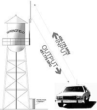
Duplex channel systems transmit and receive on different discrete channels. This defines systems where equipment cannot communicate without some infrastructure such as a repeater, base station or Talk-Through Base. Most common in the US is a repeater configuration where a base station is configured to simultaneously re-transmit the audio received from mobile units. This makes the mobiles, or hand-helds, able to communicate amongst one another anywhere within reception range of the base station or repeater. Typically the base or repeater station has a high antenna and high power, which allows much greater range, compared with a ground vehicle or hand-held transceiver.
Duplex systems can be divided into two types. The term half-duplex refers to systems where use of a push-to-talk switch is required to communicate. Full duplex refers to systems like mobile telephones with a capability to simultaneously receive and transmit. Repeaters are by nature full duplex, most mobiles and almost all handhelds are half duplex.
- Advantage: duplex channels usually allow repeater operation which extends range (in most cases due to increased transmit power and improved aerial location / height) – especially where hand-held radios are in use.
- Disadvantage: If a radio cannot reach the repeater, it cannot communicate.
Hybrid simplex/duplex[]
Some systems use a mix of the two where radios use duplex as a default but can communicate simplex on the base station channel if out-of-range.[6] In the US, the capability to talk simplex on a duplex channel with a repeater is sometimes called talk-around, direct, or car-to-car.
Push-to-talk (PTT)[]
In two-way radios with headsets, a push-to-talk button may be included on a cord or wireless electronics box clipped to the user's clothing. In fire trucks or an ambulance a button may be present where the corded headset plugs into the radio wiring. Aircraft typically have corded headsets and a separate push-to-talk button on the control yoke or control stick. Dispatch consoles often have a hand-operated push-to-talk buttons along with a foot switch or pedal. If the dispatcher's hands are on a computer keyboard, the user can step on the foot pedal to transmit. Some systems have muting so the dispatcher can be on a telephone call and the caller cannot hear what is said over the radio. Their headset microphone will mute if they transmit. This relieves the dispatcher of explaining every radio message to a caller.
In some circumstances, voice-operated transmit (VOX) is used in place of a push-to-talk button. Possible uses are handicapped users who cannot push a button, amateur radio operators, firefighters, crane operators, or others performing critical tasks where hands must be free but communication is still necessary.
Analog versus digital[]
One example of analog radios are AM aircraft radios used to communicate with control towers and air traffic controllers. Another is a Family Radio Service walkie talkie. Analog equipment is less complex than the simplest digital.
- Advantage: In high-quality equipment, better ability to communicate in cases where a received signal is weak or noisy.
- Disadvantage: Only one conversation at a time can occur on each channel.
Examples of digital communication technologies are all modern cellphones plus TETRA considered to be the best standard in digital radio and being the baseline infrastructure for whole of country networks, including manufacturers such as DAMM, Rohill, Cassidian, Sepura and others, APCO Project 25, a standard for digital public safety radios, and finally other systems such as Motorola's MotoTRBO, HQT's DMR, Nextel's iDEN, Hytera's DMR, EMC's DMR, and NXDN implemented by Icom as IDAS and by Kenwood as NEXEDGE. Only NXDN and Mototrbo are proprietary. DMR is an ETSI open standard.
- Advantage: More simultaneous talking paths are possible and information such as unit ID, status buttons, or text messages can be embedded into a single digital radio channel. The interoperability standard of TETRA means that any brand TETRA radio can work with any Brand TETRA infrastructure, not locking the user into expensive and proprietary systems.
- Disadvantage: Radios must be designed to the same, compatible standard, radios can become obsolete quickly (although this is mitigated by properly implemented interoperability standards such as those set down by ETSI for TETRA), cost more to purchase, and are more complicated.
Data over two-way radio[]
In some cases, two-way radio is used to communicate analog or digital data. Systems can be simplex or duplex and may employ selective calling features such as CTCSS. In full-duplex systems, data can be sent real-time between two points. In simplex or half-duplex, data can be sent with a time lag between many points.
Some two-way digital systems carry both audio and data over a single data stream. Systems of this type include NXDN and APCO Project 25. Other more advanced systems under the TETRA standard are capable of joining time slots together to improve data bandwidth, allowing advanced data polling and telemetry applications over radio. The method of encoding and decoding the audio stream is called a codec, such as the AMBE or the ACELP family of codecs.
After market GPS tracking and mobile messaging devices can be interfaced with popular two-way radio models providing a range of features.
Analog[]
Analog systems may communicate a single condition, such as water level in a livestock tank. A transmitter at the tank site continually sends a signal with a constant audio tone. The tone would change in pitch to indicate the tank's water level. A meter at the remote end would vary, corresponding to the tone pitch, to indicate the amount of water present in the livestock tank. Similar methods can be used to telemeter any analog condition. This type of radio system serves a purpose equivalent to a four-to-twenty milliampere loop.[7] In the US, mid-band 72–76 MHz or UHF 450–470 MHz interstitial channels are often used for these systems. Some systems multiplex telemetry of several analog conditions by limiting each to a separate range of tone pitches, for example.[8]
Digital[]
Digital systems may communicate text messages from computer-aided dispatch (CAD). For example, a display in a tow truck may give a textual location for a call and any related details. The tow truck driver may press an acknowledge button, sending data in the opposite direction and flagging the call as received by the driver. They can be used for analog telemetry systems, such as the livestock tank levels, as described above. Another possibility is the lubricating oil pressure in a transit bus engine, or the current speed of the bus. Analog conditions are translated into data words. Some systems send radio paging messages which can either 1) beep a paging receiver, 2) send a numeric message, or 3) send a text message.[9]
Digital systems typically use data rates in the 1,200–19,200 kilobit-per-second rates and may employ modulation schemes such as frequency shift keying, audio frequency shift keying, or quadrature phase shift keying to encode characters. Modern equipment have the same capabilities to carry data as are found in Internet Protocol. Working within the system's protocol constraints, virtually anything can be sent or received.
Engineered versus not engineered[]
Engineered systems are designed to perform close to a specification or standard. They are designed as systems with all equipment matched to perform together. For example, a modern, local government two-way radio system in the US may be designed to provide 95% area coverage in an urban area. System designers use radio frequency models, terrain models, and signal propagation modeling software in an attempt to accurately estimate where radios will work within a defined geographic area. The models help designers choose equipment, equipment locations, antennas, and estimate how well signals will penetrate buildings. These models will be backed-up by drive testing and actual field signal level measurements. Designers adjust antenna patterns, add or move equipment sites, and design antenna networks in a way that will accomplish the intended level of performance.[10]
Some systems are not engineered. Legacy systems are existing systems which were never designed to meet a system performance objective. They may have started with a base station and a group of mobile radios. Over a period of years, they have equipment added on in a building block style. Legacy systems may perform adequately even though they were not professionally designed as a coherent system. A user may purchase and locate a base station with an expectation that similar systems used in the past worked acceptably. A City Road Department may have a system that works acceptably, so the Parks Department may build a new similar system and find it equally usable. General Mobile Radio Service systems are not usually engineered.
Options, duty cycle, and configuration[]

1940s tube-type land mobile two-way radios often had one channel and were carrier squelch. Because radios were costly and there were fewer radio users, it might be the case that no one else nearby used the same channel. A transmit and receive crystal had to be ordered for the desired channel frequency, then the radio had to be tuned or aligned to work on the channel. 12-volt mobile, tube-type radios drew several amperes on standby and tens-of-amperes on transmit. Equipment worked ideally when new. The performance of vacuum tubes gradually degraded over time. U.S. regulations required an indicator lamp showing the transmitter had power applied and was ready to transmit and a second indicator, (usually red,) that showed the transmitter was on. In radios with options, wire jumpers and discrete components were used to select options. To change a setting, the technician soldered an option jumper wire then made any corresponding adjustments.
Many mobile and handhelds have a limited duty cycle. Duty Cycle is the ratio of listening time to transmit time and is generally dependent on how well the transmitter can shed the heat from the heat sink on the rear of the radio. A 10% duty cycle (common on handhelds) translates to 10 seconds of transmit time to 90 seconds of receive time. Some mobile and base equipment is specified at different power levels – for example 100% duty cycle at 25 watts and 15% at 40 watts.[11]
The trend is toward increasing complexity. Modern handheld and mobile radios can have capacities as high as 255 channels. Most are synthesized: the internal electronics in modern radios operate over a range of frequencies with no tuning adjustments. High-end models may have several hundred optional settings and require a computer and software to configure. Sometimes, controls on the radio are referred to as programmable. By changing configuration settings, a system designer could choose to set up a button on the radio's control panel to function as:
- turn scan on or off,
- alert another mobile radio, (selective calling),
- turn on an outside speaker, or
- select repeater locations.
In most modern radios these settings are done with specialized software (provided by the manufacturer) and a connection to a laptop computer.
Microprocessor-based radios can draw less than 0.2 amperes on standby and up to tens-of-amperes on high-powered, 100 watt transmitters.

Base stations, repeaters, and high-quality mobile radios often have specifications that include a duty cycle. A repeater should always be continuous duty. This means the radio is designed to transmit in a continuous broadcast without transmitter overheating and resulting failure. Handhelds are intermittent duty, mobile radios and base station radios are available in normal or continuous duty configurations. Continuous duty is preferred in mobile emergency equipment because any one of an entire fleet of ambulances, for example, could be pressed into service as command post at a major incident. Unfortunately budgets frequently get in the way and intermittent duty radios are purchased.
Time delay is always associated with radio systems, but it is apparent in spacecraft communications. NASA regularly communicates with exploratory spacecraft where a round-trip message time is measured in hours (like out past Jupiter). For the Apollo program and the Space Shuttle, Quindar tones were used for transmit PTT control.
Life of equipment[]
Though the general life term for the two-way radio is 5 to 7 years and 1 to 2 years for its accessories but still the usage, atmosphere and environment plays a major role to decide its life term (radios are often deployed in harsh environments where more fragile communication equipment such as phones and tablets may fail). There are so many speculations on the life term of two-way radios and their accessories i.e. batteries, chargers, headset etc.
In government systems, equipment may be replaced based on budgeting rather than any plan or expected service life. Funding in government agencies may be cyclical or sporadic. Managers may replace computing systems, vehicles, or budget computer and vehicle support costs while ignoring two-way radio equipment. Equipment may remain in use even though maintenance costs are unreasonable when viewed from an efficiency standpoint.[12]
Different system elements will have differing service lifetimes. These may be affected by who uses the equipment. An individual contacted at one county government agency claimed equipment used by 24-hour services wears out much faster than equipment used by those who work in positions staffed eight hours a day.
One document says "seven years" is beyond the expected lifetime of walkie-talkies in police service. Batteries are cited as needing replacement more often. Twelve-year-old dispatch consoles mentioned in the same document were identified as usable. These were compared to problematic 21-year-old consoles used elsewhere in the same system.[13]
Another source says system backbone equipment like consoles and base stations are expected to have a fifteen-year life. Mobile radios are expected to last ten years. Walkie talkies typically last eight.[14] In a State of California document, the Department of General Services reports expected service life for a communications console used in the Department of Forestry and Fire Protection is 10 years.[15]
Two-way radio rental is an option for firms that need use of radios for only a limited time.
Two-way radio frequencies[]
The examples and perspective in this section deal primarily with the United States and do not represent a worldwide view of the subject. (October 2012) |
Two-way radios can operate on many different frequencies, and these frequencies are assigned differently in different countries. Typically channelized operations are used, so that operators need not tune equipment to a particular frequency but instead can use one or more pre-selected frequencies, easily chosen by a dial, a pushbutton or other means. For example, in the United States, there is a block of 5 channels (pre-selected radio frequencies) are allocated to the Multiple Use Radio System. A different block of 22 channels are assigned, collectively, to the General Mobile Radio Service and Family Radio Service. The citizen's band radio service (""CB"") has 40 channels.
In an analog, conventional system, (the simplest type of system) a frequency or channel serves as a physical medium or link carrying communicated information. The performance of a radio system is partly dependent on the characteristics of frequency band used. The selection of a frequency for a two-way radio system is affected, in part, by:[16]
- government licensing and regulations.
- local congestion or availability of frequencies.
- terrain, since radio signals travel differently in forests and urban viewsheds.
- the presence of noise, interference, or intermodulation.
- sky wave interference below 50–60 MHz and tropospheric bending at VHF.
- in the US, some frequencies require approval of a frequency coordination committee.
A channel number is just a shorthand notation for a frequency. It is, for instance, easier to remember "Channel 1" than to remember "26.965 MHz" (US CB Channel 1) or "462.5625 MHz" (FRS/GMRS channel 1), or "156.05 MHz" (Marine channel 1). It is necessary to identify which radio service is under discussion when specifying a frequency by its channel number. Organizations such as electric power utilities or police departments may have several assigned frequencies in use with arbitrarily assigned channel numbers. For example, one police department's "Channel 1" might be known to another department as "Channel 3" or may not even be available. Public service agencies have an interest in maintaining some common frequencies for inter-area or inter-service coordination in emergencies (modern term: interoperability).
Each country allocates radio frequencies to different two-way services, in accordance with international agreements. In the United States, some examples of two-way services are: citizen's band radio, Digital Electronic Message Service (DEMS), Family Radio Service (FRS), General Mobile Radio Service (GMRS), Multi-Use Radio Service (MURS), Business Radio Service (BRS), and PMR446.
Amateur radio operators nearly always use frequencies rather than channel numbers, since there is no regulatory or operating requirement for fixed channels in this context. Even amateur radio equipment will have "memory" features to allow rapidly setting the transmitter and receiver to favorite frequencies.
UHF versus VHF[]
The most common two-way radio systems operate in the VHF and UHF parts of the radio spectrum. Because this part of the spectrum is heavily used for broadcasting and multiple competing uses, spectrum management has become an important activity of governments to regulate radio users in the interests of both efficient and non-interfering use of radio. Both bands are widely applied for different users.
UHF has a shorter wavelength which makes it easier for the signal to find its way through smaller wall openings to the inside of a building. The longer wavelength of VHF means it can transmit further under normal conditions. For most applications, lower radio frequencies are better for longer range and through vegetation. A broadcasting TV station illustrates this. A typical VHF TV station operates at about 100,000 watts and has a coverage radius range of about 60 miles. A UHF TV station with a 60-mile coverage radius requires transmitting at 3,000,000 watts. Another factor with higher frequencies (UHF) is that smaller sized objects will absorb or reflect the energy more which causes range loss and/or multipath reflections which can weaken a signal by causing an "Out of Time/Out of Phase" signal to reach the antenna of the receiver (this is what caused the "Ghost" image on old over the air television).
If an application requires working mostly outdoors, a VHF radio is probably the best choice, especially if a base station radio indoors is used and an external antenna is added. The higher the antenna is placed, the further the radio can transmit and receive.
If the radios are used mainly inside buildings, then UHF is likely the best solution since its shorter wavelength travels through small openings in the building better. There are also repeaters that can be installed that can relay any frequencies signal (VHF or UHF) to increase the communication distance.
There are more available channels with UHF. Since the range of UHF is also not as far as VHF under most conditions, there is less chance of distant radios interfering with the signal. UHF is less affected than VHF by manmade electrical noise.
Range[]
The useful direct range of a two-way radio system depends on radio propagation conditions, which are a function of frequency,[17] antenna height and characteristics, atmospheric noise, reflection and refraction within the atmosphere, transmitter power and receiver sensitivity, and required signal-to-noise ratio for the chosen modulation method. An engineered two-way radio system will calculate the coverage of any given base station with an estimate of the reliability of the communication at that range. Two-way systems operating in the VHF and UHF bands, where many land mobile systems operate, rely on line-of-sight propagation for the reliable coverage area. The "shadowing" effect of tall buildings may block reception in areas within the line-of-sight range which can be achieved in open countryside free of obstructions. The approximate line-of-sight distance to the radio horizon can be estimated from: horizon in kilometers = 3.569 times the square root of the antenna height in meters.
There are other factors that affect the range of a two-way radio such as weather, exact frequency used, and obstructions.[17][18]
Other two-way radio devices[]
Not all two-way radios are hand-held devices. The same technology that is used in two-way radios can be placed in other radio forms. An example of this is a wireless callbox. A wireless callbox is a device that can be used for voice communication at security gates and doors. Not only can they be used to talk to people at these entry points, personnel can remotely unlock the door so the visitor can enter. There are also customer service callboxes that can be placed around a business that a customer can use to summon help from a two-way radio equipped store employee.
Another use of two-way radio technology is for a wireless PA system. A wireless PA is essentially a one-way two-way radio that enables broadcasting messages from handheld two-way radios or base station intercoms.
See also[]
- TETRA (Terrestrial Trunked Radio)
- Astro (Motorola)
- Digital Mobile Radio
- PMR446
- Family Radio Service
- GE Marc V
- Project 25
- Quik Call I
- Motorola Saber
- Mobile radio
- Professional Mobile Radio
- Specialized Mobile Radio
- Mobile radio telephone
- Radiotelephony
References[]
- ^ Goldsmith, Andrea (8 Aug 2005). Wireless Communications. Cambridge University Press. ISBN 9780521837163. Retrieved 20 April 2016.
- ^ Haldane, Robert. (1995) The People's Force, A history of the Victoria Police. Melbourne University Press. ISBN 0-522-84674-2, 1995
- ^ IEEE History Milestones retrieved Oct. 2, 2007
- ^ One example of purpose-specific channel assignments is described in Ivanov, D. A., V. P. Savelyev, and P. V. Shemanski, "Organization of Communications," Fundamentals of Tactical Command and Control: A Soviet View, Soviet Military Thought Series #18, (Washington, D.C.: Superintendent of Documents, 1977) Library of Congress Control Number: 84602565. This is a US Air Force translation of a Soviet-era, Russian-language book. See also, "Inadequate System Capacity," Special Report: Improving Firefighter Communications, USFA-TR-099/January 1999, (Emmitsburg, Maryland: U.S. Fire Administration, 1999) pp. 18-19 and "5.2 Present System," The California Highway Patrol Communications Technology Research Project on 800 MHz, 80-C477, (Sacramento, California: Department of General Services, Communications Technology Division, 1982,) pp. V-4 - V-6.
- ^ "3.4.1 User Equipment General Deficiencies," San Rafael Police Radio Committee: Report to Mayor and City Council, (San Rafael, California: City of San Rafael, 1995,) pp. 12.
- ^ For an example of talk around use, see "Problem Reporting," Special Report: Improving Firefighter Communications, USFA-TR-099/January 1999, (Emmitsburg, Maryland: U.S. Fire Administration, 1999) pp. 25-26. This article also confirms the definition of the phrase talk around.
- ^ For examples, see, Mikhailov, K. E. "Communications Facilities on the Volga-Moscow Transmission Line," Long-Distance Electrical Transmission between the V. I. Lenin Hydroelectric Station and Moscow, (Jerusalem: Israeli Program for Scientific Translations, 1965).
- ^ For an electrocardiogram telemetry example, see Planning Emergency Medical Communications: Volume 2, Local/Regional-Level Planning Guide, (Washington, D.C.: National Highway Traffic Safety Administration, US Department of Transportation, 1995) pp. 48.
- ^ "Spartan Training Bulletin - Volume One – Issue One". Retrieved October 18, 2017.
- ^ For two examples of drive testing and field measurements of received signal levels, see:
- "Section II: Radio Propagation Studies," The California Highway Patrol Communications Technology Research Project on 800 MHz, 80-C477, (Sacramento, California: Department of General Services, Communications Technology Division, 1982,) pp. II-1 - II-34.
- Ossanna, Jr., Joseph F., "A Model For Mobile Radio Fading Due to Building Reflections: Theoretical and Experimental Fading Waveform Power Spectra," Bell System Technical Journal, November 1964, pp. 2935-2971. 800 MHz trivia: this article shows that signal fades occur at audio frequencies near CTCSS tones, explaining why only DCS was used in Motorola 800 MHz systems in the 1970s.
- ^ Kenwood TKR-850 specification sheet
- ^ For one example, see: "Plan Element S-7: Rationalized Funding" and "Plan Element L-2: Permanent Contra Costa Public Safety Radio Authority," Contra Costa County Public Safety Mobile Radio Master Plan, (Fairfax, Virginia: Federal Engineering, Inc., 2002,) pp. 45, 49.
- ^ For one example, see: "3.2.10.1 Current System Problems," Trunked Radio System: Request For Proposals, (Oklahoma City, Oklahoma: Oklahoma City Municipal Facilities Authority, Public Safety Capital Projects Office, 2000) pp. 56.
- ^ "2.4 Equipment Inventory," San Rafael Police Radio Committee: Report to Mayor and City Council, (San Rafael, California: City of San Rafael, 1995,) pp. 8.
- ^ "8000 Exhibits:Equipment Replacement Costs for a Typical Three Position CDF Command and Control Center," 8000 Telecommunications Manual, (Sacramento, California: State of California, Department of Forestry and Fire Protection, 2006) Adobe PDF file on console costs.
- ^ See, "Appendix B - FCC Regulations," California EMS Communications Plan: Final Draft, (Sacramento, California: State of California EMS Authority, September 2000) pp.38. and Arizona Phase II Final Report: Statewide Radio Inter-operability Needs Assessment, Macro Corporation and The State of Arizona, 2004.
- ^ Jump up to: a b Two Way Radio Range
- ^ "2-Way Radio Range: How Far Can Two-Way Radios Communicate?"
External links[]
| show Telecommunications |
|---|
| show Authority control |
|---|
- Radio communications