Logic optimization
Logic optimization, a part of logic synthesis in electronics, is the process of finding an equivalent representation of the specified logic circuit under one or more specified constraints. Generally the circuit is constrained to minimum chip area meeting a prespecified delay.
Introduction[]
With the advent of logic synthesis, one of the biggest challenges faced by the electronic design automation (EDA) industry was to find the best netlist representation of the given design description. While two-level logic optimization had long existed in the form of the Quine–McCluskey algorithm, later followed by the Espresso heuristic logic minimizer, the rapidly improving chip densities, and the wide adoption of HDLs for circuit description, formalized the logic optimization domain as it exists today.
Today, logic optimization is divided into various categories:
Based on circuit representation
- Two-level logic optimization
- Multi-level logic optimization
Based on circuit characteristics
- Sequential logic optimization
- Combinational logic optimization
Based on type of execution
- Graphical optimization methods
- Tabular optimization methods
- Algebraic optimization methods
While a of circuits strictly refers to the flattened view of the circuit in terms of SOPs (sum-of-products) — which is more applicable to a PLA implementation of the design[clarification needed] — a is a more generic view of the circuit in terms of arbitrarily connected SOPs, POSs (product-of-sums), factored form etc. Logic optimization algorithms generally work either on the structural (SOPs, factored form) or functional (BDDs, ADDs) representation of the circuit.[clarification needed]
Two-level versus multi-level representations[]
If we have two functions F1 and F2:


The above 2-level representation takes six product terms and 24 transistors in CMOS Rep.[why?]
A functionally equivalent representation in multilevel can be:
- P = B + C.
- F1 = AP + AD.
- F2 = A'P + A'E.
While the number of levels here is 3, the total number of product terms and literals reduce[quantify] because of the sharing of the term B + C.
Similarly, we distinguish between sequential and combinational circuits, whose behavior can be described in terms of finite-state machine state tables/diagrams or by Boolean functions and relations respectively.[clarification needed]
Circuit minimization in Boolean algebra[]
In Boolean algebra, circuit minimization is the problem of obtaining the smallest logic circuit (Boolean formula) that represents a given Boolean function or truth table. For the case when the Boolean function is specified by a circuit (that is, we want to find an equivalent circuit of minimum size possible), the unbounded circuit minimization problem was long-conjectured to be -complete, a result finally proved in 2008,[1] but there are effective heuristics such as Karnaugh maps and the Quine–McCluskey algorithm that facilitate the process.

Boolean function minimizing methods include:
- –Poretsky method
- [2][3][4][5][6]
- Quine–McCluskey algorithm
- method of algebraic transformations
- Petrick's method
- Roth method[7][8][9]
- Kudielka method[10][11][12]
- Wells method[13]
- Scheinman's binary method[14][15]
- a method of minimizing functions in bases YES-NO and OR-NOT (Schaeffer and Pierce basis)
- method of undetermined coefficients
- hypercube method
- functional decomposition method
- Espresso heuristic logic minimizer
Purpose[]
The problem with having a complicated circuit (i.e. one with many elements, such as logic gates) is that each element takes up physical space in its implementation and costs time and money to produce in itself. Circuit minimization may be one form of logic optimization used to reduce the area of complex logic in integrated circuits.
Example[]
While there are many ways to minimize a circuit, this is an example that minimizes (or simplifies) a Boolean function. Note that the Boolean function carried out by the circuit is directly related to the algebraic expression from which the function is implemented.[16] Consider the circuit used to represent . It is evident that two negations, two conjunctions, and a disjunction are used in this statement. This means that to build the circuit one would need two inverters, two AND gates, and an OR gate.

We can simplify (minimize) the circuit by applying logical identities or using intuition. Since the example states that A is true when B is false or the other way around, we can conclude that this simply means . In terms of logical gates, inequality simply means an XOR gate (exclusive or). Therefore, . Then the two circuits shown below are equivalent:


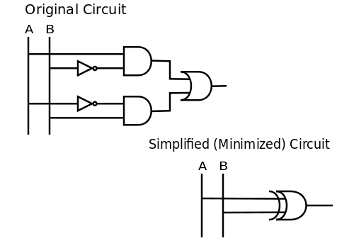
You can additionally check the correctness of the result using a truth table.
Graphical logic minimization methods[]
Graphical minimization methods for two-level logic include:
- Euler diagram (aka Eulerian circle) (1768) by Leonhard P. Euler (1707–1783)
- Venn diagram (1880) by John Venn (1834–1923)[17][18]
- Marquand diagram (1881) by Allan Marquand (1853–1924)[19][20]
- Harvard minimizing chart (aka Harvard chart) (1951) by Howard H. Aiken (1900–1973) and Martha L. Whitehouse[21][22][23][24][15] of the Harvard Computation Laboratory
- Decomposition chart (1952) by Robert L. Ashenhurst (1929–2009) and Theodore Singer (1916–1991)[25][26][27][24] of the Harvard Computation Laboratory
- Veitch chart (1952) by Edward W. Veitch (1924–2013)[28][20]
- Karnaugh map (1953) by Maurice Karnaugh (1924–)[22][24]
- Contact bones, contact grids (1955), and the triadic map by Antonín Svoboda (1907–1980)[29][30][31][32][33][34][35][36][37][38][39][40][41][42]
- Graphical method (1957) by Vadim Nikolaevich Roginskij[43] [Вадим Николаевич Рогинский] (1913–1983)[44][45][46][36]
- Händler diagram (aka Händler circle graph, Händler'scher Kreisgraph, Kreisgraph nach Händler, Händler-Kreisgraph, Händler-Diagramm, Minimisierungsgraph, Mn graph) (1958) by Wolfgang Händler (1920–1998)[47][48][49][41][50][51][52][53][54][55][56][57][58]
- Mahoney map aka M-map or designation numbers (1963) by Matthew V. Mahoney[59][60][61][62][63][64][65][66][67][68][69][70][71]
- Graph method (1965) by (1907–1979)[72][73][74][75][76][77][78][79][80][81]
- Reduced Karnaugh map (RKM)[82][83][84] techniques aka infrequent variables (1969) by G. W. Schultz,[85][86][87] map-entered variables (MEV, 1969) by [86] and Christopher R. Clare,[88][89][90][91][92][93][94][95][83][84] Karnaugh map with letter-name variables (1972) by J. Robert Burgoon[82][96] and Larry L. Dornhoff (1942–2017),[90] variable-entered Karnaugh map (VEKM, 1983) by Ali M. Rushdi (1951–),[97][98][99][100][101][102][96] variable-entered map (VEM) by William I. Fletcher (1938–2020)[91][103] or variable entrant map (VEM)[104]
- Hypercube method (1982) by Stamatios V. Kartalopoulos[105]
- Minterm-ring map (MRM) or Minterm-ring algorithm (1990) by Thomas R. McCalla[106][95][107][103]
- V diagram (2001) by Jonathan Westphal (1951–)[108][109]
- Paraboomig (2003) by Shrish Verma and Kiran D. Permar[110][111]
- Majority-inverter graph (MIG) (2014) by Luca Amarú, Pierre-Emmanuel Gaillardon and Giovanni De Micheli[112][113]
- Pandit plot (2017) by Vedhas Pandit and Björn W. Schuller (1975–)[114]
- Truth graph (2020) by Eisa Alharbi[115][116]
See also[]
- Binary decision diagram (BDD)
- Don't care condition
- Prime implicant
- Circuit complexity
- Function composition
- Function decomposition
- Gate underutilization
- Harvard minimizing chart (Wikiversity) (Wikibooks)
References[]
- ^ Buchfuhrer, David; Umans, Christopher (January 2011). "The complexity of Boolean formula minimization" (PDF). Journal of Computer and System Sciences (JCSS). Computer Science Department, California Institute of Technology, Pasadena, California, USA: Elsevier Inc. 77 (1): 142–153. doi:10.1016/j.jcss.2010.06.011. This is an extended version of the conference paper: Buchfuhrer, David; Umans, Christopher (2008). "The Complexity of Boolean Formula Minimization". Proceedings of Automata, Languages and Programming (PDF). 35th International Colloquium (ICALP). Lecture Notes in Computer Science (LNCS). 5125. Berlin / Heidelberg, Germany: Springer-Verlag. pp. 24–35. doi:10.1007/978-3-540-70575-8_3. ISBN 978-3-540-70574-1. Archived (PDF) from the original on 2018-01-14. Retrieved 2018-01-14.
- ^ Nelson, Raymond J. (June 1955). "Simplest Normal Truth Functions". Journal of Symbolic Logic. Association for Symbolic Logic. 20 (2): 105–108. doi:10.2307/2266893. JSTOR 2266893. (4 pages) (NB. A method converting a conjunctive normal form into a disjunctive normal form, followed by a procedure similar to Quine's.)
- ^ Nelson, Raymond J. (September 1955). "Weak Simplest Normal Truth Functions". Journal of Symbolic Logic. Association for Symbolic Logic. 20 (3): 232–234. doi:10.2307/2268219. JSTOR 2268219. (3 pages)
- ^ Lipp, Hans Martin; Becker, Jürgen (2011). Grundlagen der Digitaltechnik (in German) (reworked 7th ed.). Munich, Germany: / Walter de Gruyter. ISBN 9783486706932. ISBN 3486706934. Retrieved 2020-05-12. (316 pages)
- ^ Riznyk, Volodymyr; Solomko, Mykhailo (July 2017). "Minimization of Boolean functions by combinatorial method". Information and Control Systems: Mathematical Modeling (in English and Russian). 4/2 (36): 49–64. doi:10.15587/2312-8372.2017.108532. ISSN 2226-3780. UDC 681.325. Archived (PDF) from the original on 2020-05-12. Retrieved 2020-05-12.
- ^ Riznyk, Volodymyr; Solomko, Mykhailo (July 2018). "Minimization of Conductive Normal Forms of Boolean Functions by Combinatorial Method" (PDF). Information and Control Systems: Mathematical Modeling (in English and Russian). 5/2 (43): 42–55. doi:10.15587/2312-8372.2018.146312. ISSN 2226-3780. UDC 681.325. Archived (PDF) from the original on 2020-05-12. Retrieved 2020-05-12.
- ^ Roth, John Paul (July 1959) [April 1957-04-02/05]. "Algebraic topological methods in synthesis". Proceedings of an International Symposium on the Theory of Switching, Part I. The Annals of the Harvard Computation Laboratory. Cambridge, Massachusetts, USA: Harvard University Press. XXIX: 57–73.
- ^ Roth, John Paul (July 1958). "Algebraic Topological Methods for the Synthesis of Switching Systems, Part I". Transactions of the American Mathematical Society. 88 (2): 301–326. doi:10.2307/1993216. JSTOR 1993216. (26 pages)
- ^ Roth, John Paul (November 1960). "Minimization over Boolean Trees". IBM Journal of Research and Development. 4 (5): 543–558. doi:10.1147/rd.45.0543. eISSN 0018-8646. ISSN 0018-8646.
- ^ Kudielka, Viktor; Walk, Kurt; Bandat, Kurt; Lucas, Peter; Zemanek, Heinrich "Heinz" Josef (1960-02-29). "4–5". In Zemanek, Heinrich "Heinz" Josef (ed.). Programs for Logical Data Processing. Mailüfterl (Final report). Vienna, Austria: Technical University of Vienna, Institut für Nachrichtentechnik. European Research Office Contract DA-91-591-EC-1062. Retrieved 2020-05-29. (198 pages)
- ^ Kudielka, Viktor; Lucas, Peter; Walk, Kurt; Bandat, Kurt; Bekic, Heinz; Zemanek, Heinrich "Heinz" Josef (1961-07-31). "2". Extension of the Algorithmic Language ALGOL (Final Report). European Research Office Contract DA-91–591-EUC-1430.
- ^ Kudielka, Viktor (January 1963) [1961-10-18]. "Programmierung von Minimisierungsverfahren für zweistufige Logik". In Dörr, Johannes; Peschl, Ernst Ferdinand; Unger, Heinz (eds.). 2. Colloquium über Schaltkreis- und Schaltwerk-Theorie - Vortragsauszüge vom 18. bis 20. Oktober 1961 in Saarbrücken. Internationale Schriftenreihe zur Numerischen Mathematik [International Series of Numerical Mathematics] (ISNM) (in German). 4 (2013-12-20 reprint of 1st ed.). Institut für Angewandte Mathematik, Universität Saarbrücken, Rheinisch-Westfälisches Institut für Instrumentelle Mathematik: Springer Basel AG / Birkhäuser Verlag Basel. pp. 49–65. doi:10.1007/978-3-0348-4156-6. ISBN 978-3-0348-4081-1. Retrieved 2020-04-15. (152 pages)
- ^ Wells, Mark B. (1962). "Chapter 14. Switching Theory: Application of a Finite Set Covering Theorem to the Simplification of Boolean Function Expressions". Information Processing, Proceedings of the 2nd IFIP Congress 1962, Munich, Germany, August 27 - September 1, 1962. 2. Munich, Germany: North-Holland. pp. 731–735. Retrieved 2020-05-28.
- ^ Scheinman, Arnold H. (July 1962) [1962-03-06]. "A Method For Simplifying Boolean Functions". Bell System Technical Journal. Nokia Bell Labs. 41 (4): 1337–1346. doi:10.1002/j.1538-7305.1962.tb03280.x. ISSN 0005-8580. [1] (NB. Also known as Scheinman's binary method, this is an easy to use iterative method also for large functions, which will result in significantly simplified functions, but not necessarily in the simplest. The author is sometimes misspelled as "Schienmann".)
- ^ Jump up to: a b Föllinger, Otto; Weber, Wolfgang (1967) [June 1965]. "5.4. Die Methode der Harvard Group of Computation / 5.5 Vereinfachungsmethode nach Scheinman". Written at Frankfurt am Main, Germany. Methoden der Schaltalgebra (in German) (1 ed.). Munich, Germany: . pp. 103, 120, 122–128, 128–135. (6+320+6 pages)
- ^ Mano, M. Morris; Kime, Charles R. (2014). Logic and Computer Design Fundamentals (4th new international ed.). Pearson Education Limited. p. 54. ISBN 978-1-292-02468-4.
- ^ Venn, John (July 1880). "I. On the Diagrammatic and Mechanical Representation of Propositions and Reasonings" (PDF). The London, Edinburgh, and Dublin Philosophical Magazine and Journal of Science. 5. 10 (59): 1–18. doi:10.1080/14786448008626877. Archived (PDF) from the original on 2017-05-16. [2] [3]
- ^ Venn, John (1880). "On the employment of geometrical diagrams for the sensible representations of logical propositions". Proceedings of the Cambridge Philosophical Society. 4: 47–59.
- ^ Marquand, Allan (1881). "XXXIII: On Logical Diagrams for n terms". The London, Edinburgh, and Dublin Philosophical Magazine and Journal of Science. 5. 12 (75): 266–270. doi:10.1080/14786448108627104. (NB. Quite many secondary sources erroneously cite this work as "A logical diagram for n terms" or "On a logical diagram for n terms".)
- ^ Jump up to: a b Brown, Frank Markham (2012) [2003, 1990]. Boolean Reasoning - The Logic of Boolean Equations (reissue of 2nd ed.). Mineola, New York: Dover Publications, Inc. ISBN 978-0-486-42785-0. ISBN 0-486-42785-4. First Edition PDF
- ^ Aiken, Howard Hathaway; Blaauw, Gerrit Anne; Burkhart, William; Burns, Robert J.; Cali, Lloyd; Canepa, Michele; Ciampa, Carmela M.; Coolidge, Jr., Charles A.; Fucarile, Joseph R.; Gadd, Jr., J. Orten; Gucker, Frank F.; Harr, John A.; Hawkins, Robert L.; Hayes, Miles V.; Hofheimer, Richard; Hulme, William F.; Jennings, Betty L.; Johnson, Stanley A.; Kalin, Theodore; Kincaid, Marshall; Lucchini, E. Edward; Minty, William; Moore, Benjamin L.; Remmes, Joseph; Rinn, Robert J.; Roche, John W.; Sanbord, Jacquelin; Semon, Warren L.; Singer, Theodore; Smith, Dexter; Smith, Leonard; Strong, Peter F.; Thomas, Helene V.; Wang, An; Whitehouse, Martha L.; Wilkins, Holly B.; Wilkins, Robert E.; Woo, Way Dong; Little, Elbert P.; McDowell, M. Scudder (1952) [January 1951]. "Chapter V: Minimizing charts". Synthesis of electronic computing and control circuits. The Annals of the Computation Laboratory of Harvard University. XXVII (second printing, revised ed.). Write-Patterson Air Force Base: Harvard University Press (Cambridge, Massachusetts, USA) / Geoffrey Cumberlege Oxford University Press (London). pp. preface, 50–67. ark:/13960/t4zh1t09d. Retrieved 2017-04-16. p. preface:
[…] Martha Whitehouse constructed the minimizing charts used so profusely throughout this book, and in addition prepared minimizing charts of seven and eight variables for experimental purposes. […] Hence, the present writer is obliged to record that the general algebraic approach, the switching function, the vacuum-tube operator, and the minimizing chart are his proposals, and that he is responsible for their inclusion herein. […]
(2+x+278+2 pages) (NB. Work commenced in April 1948.) - ^ Jump up to: a b Karnaugh, Maurice (November 1953) [1953-04-23, 1953-03-17]. "The Map Method for Synthesis of Combinational Logic Circuits" (PDF). Transactions of the American Institute of Electrical Engineers, Part I: Communication and Electronics. 72 (5): 593–599. doi:10.1109/TCE.1953.6371932. Paper 53-217. Archived from the original (PDF) on 2017-04-16. Retrieved 2017-04-16.
- ^ Phister, Jr., Montgomery (April 1959) [December 1958]. Logical design of digital computers. Digital Design and Applications (3rd printing, 1st ed.). New York, USA: John Wiley & Sons Inc. pp. 75–83. ISBN 0-47168805-3. LCCN 58-6082. MR 0093930. ISBN 978-0-47168805-1. (xvi+408 pages)
- ^ Jump up to: a b c Curtis, Herbert Allen (1962). A new approach to the design of switching circuits. The Bell Laboratories Series (1 ed.). Princeton, New Jersey, USA: D. van Nostrand Company, Inc. ISBN 0-44201794-4. OCLC 1036797958. S2CID 57068910. ISBN 978-0-44201794-1. ark:/13960/t56d6st0q. (viii+635 pages) (NB. This book was reprinted by Chin Jih in 1969.)
- ^ Ashenhurst, Robert "Bob" Lovett (January 1953) [1952-09-01, 1953-01-01]. "The decomposition of switching functions". Bell Laboratories' Report (report). Harvard Computation Laboratory, Harvard University, Cambridge, Massachusetts, USA: Bell Laboratories (BL-1): II-1–II-37. PB122812. (37 of 98 pages) (NB. This article was reprinted in the appendix of Curtis (1962), pp. 571–602.); another article of the same title was published as: Ashenhurst, Robert "Bob" Lovett (December 1956) [1956-05-01, 1956-12-01]. Aiken, Howard Hathaway (ed.). "The decomposition of switching functions". Bell Laboratories' Report / Theory of Switching (report). Harvard Computation Laboratory, Harvard University, Cambridge, Massachusetts, USA: Bell Laboratories (BL-16): III-1–III-72. PB147348. (72 of 193 pages); an updated article was later published under the same title as: Ashenhurst, Robert "Bob" Lovett (1957-04-02). "The Decomposition of Switching Functions" (PDF). Proceedings of the International Symposium on the Theory of Switching, Part I. The Annals of the Computation Laboratory of Harvard University. Harvard University, Cambridge, Massachusetts, USA: Harvard University Press (published 1959). XXIX: 74–116. Archived (PDF) from the original on 2021-03-28. Retrieved 2021-03-29. (43 pages)
- ^ Singer, Theodore "Ted" (July 1953) [1953-04-01, 1953-07-01]. "The Decomposition Chart as a Theoretical Aid". Bell Laboratories' Report (report). Harvard Computation Laboratory, Harvard University, Cambridge, Massachusetts, USA: Bell Laboratories (BL-4): III-1–III-28. PB122815. (28 of 149 pages) (NB. This article was reprinted in the appendix of Curtis (1962), pp. 602–620.)
- ^ Ashenhurst, Robert "Bob" Lovett (July 1953) [1953-04-01, 1953-07-01]. "Non-disjoint Decomposition". Bell Laboratories' Report (report). Harvard Computation Laboratory, Harvard University, Cambridge, Massachusetts, USA: Bell Laboratories (BL-4): IV-1–IV-12. PB122815. (12 of 149 pages) (NB. This article was reprinted in the appendix of Curtis (1962), pp. 620–630.)
- ^ Veitch, Edward Westbrook (1952-05-03) [1952-05-02]. "A Chart Method for Simplifying Truth Functions". Transactions of the 1952 ACM Annual Meeting. ACM Annual Conference/Annual Meeting: Proceedings of the 1952 ACM Annual Meeting (Pittsburgh, Pennsylvania, USA). New York, USA: Association for Computing Machinery (ACM): 127–133. doi:10.1145/609784.609801.
- ^ Svoboda, Antonín (1955-11-27) [1955-11-22]. Graphisch-mechanische Hilfsmittel für die Synthese von Relaisschaltungen [Graphical-mechanical aids for the synthesis of relay circuits] (Report). Dresden, Germany: Internationales Mathematiker-Kolloquium über aktuelle Probleme der Rechentechnik. pp. 43–50. (NB. According to Constantinescu the contents might be identical to a journal article in 1956.)
- ^ Svoboda, Antonín (1956). Graficko-mechanické pomůcky užívané při analyse a synthese kontaktových obvodů [Utilization of graphical-mechanical aids for the analysis and synthesis of contact circuits]. Stroje na zpracování informací [Symposium on information processing machines] (in Czech). IV. Prague: Czechoslovak Academy of Sciences, Research Institute of Mathematical Machines. pp. 9–22.CS1 maint: date and year (link)
- ^ Svoboda, Antonín (1956). (unknown) [Graphical-Mechanical Aids for the Synthesis of Relay Circuits]. Nachrichtentechnische Fachberichte (NTF), Beihefte der Nachrichtentechnischen Zeitschrift (NTZ) (in Czech). 4. Braunschweig, Germany: Friedrich Vieweg & Sohn. pp. 213–218. ECIP55 213. Cite uses generic title (help)CS1 maint: date and year (link) (NB. According to Constantinescu the contents might be identical to a congress report in 1955.)
- ^ Svoboda, Antonín (1959) [1957-03-29]. "Some Applications of Contact Grids". Proceedings of an International Symposium on the Theory of Switching, 2–5 April 1957, Part I. The Annals of the Computation Laboratory of Harvard University. XXIX. Harvard University, Cambridge, Massachusetts, USA: Harvard University Press. pp. 293–305. (305 pages)
- ^ Svoboda, Antonín (1958). (unknown) [Graphical aids to minimization in switching circuits]. Stroje na zpracování informací [Symposium on information processing machines] (in Czech). VI. Prague: Czechoslovak Academy of Sciences, Research Institute of Mathematical Machines. pp. 35–53. Cite uses generic title (help)
- ^ McNaughton, Robert Forbes (March 1958). "Antonin Svoboda. Graphico-mechanical aids for the synthesis of relay circuits. Aktuelle Probleme der Rechentechnik, Deutscher Verlag der Wissenschaften, Berlin 1957, pp. 43–50". Journal of Symbolic Logic (Review). 23 (1): 60–61. doi:10.2307/2964502. Retrieved 2020-05-14. p. 60:
The two graphico-mechanical aids are contact bones and contact grids. Contact bones are an aid in analyzing (i.e., finding a logical formula for) contact networks. The logical theory of contact network analysis has been generally understood for a long time, but there are practical difficulties, especially in the analysis of bridge networks (i.e., networks which are not of the series-parallel type). Contact grids are an aid in obtaining a normal formula for functions given in truth-table form. They are helpful in obtaining what are called (by others) prime implicants. […]
(NB. This review is about Svoboda's congress report.) - ^ Constantinescu, Paul (1959-12-22). "Svoboda, Antonin. Graphical-mechanical aids for the synthesis of relay circuits. Elektronische Rechenmaschinen und Informationsverarbeitung, 213–218 (1956). — Ber. Internat. Math.-Kolloquium Dresden, 22. bis 27. Nov. 1955, 42–50 (1957)". Zentralblatt für Mathematik (Review). 82 (1): 126. Zbl 0082.12602. Archived from the original on 2020-05-14. Retrieved 2020-05-14. p. 126:
The author utilizes interesting mechanical aids in solving problems concerning contact networks. The basis for the creation of these aids is the fact that each independent variable may be expressed by a Boolean sum of variables which define the state of the network. Employing "contact bones" and "contact grids" the author achieves the analysis and synthesis of a contact network and the transformation of the Boolean functions given in tabular form in algebraic form.
(NB. This review is about Svoboda's congress report and journal article.) - ^ Jump up to: a b Roginskij [Рогинский], Vadim Nikolaevich [Вадим Николаевич] (1962). Grundlagen der Struktursynthese von Relaisschaltungen (in German). Translated by Hausenblas, Albin; Pfaffinger, Robert; Resele, H. (1st German ed.). Munich, Germany: . OCLC 968499019. OCLC 163791522. Retrieved 2002-05-30 (204 pages). This book is a translation of the original work: Roginskij [Рогинский], Vadim Nikolaevich [Вадим Николаевич] (1959). Kharkevich [Харкевич], Aleksandr Aleksandrovich [Александр Александрович] (ed.). Ėlementy strukturnogo sinteza releĭnykh skhem upravlenii︠a︡ Элементы структурного синтеза релейных схем управления (in Russian) (1st ed.). Moscow: Изд-во Академии наук СССР (Izdatel'stvo akademii nauk SSSR) [4]. Also available in English as: Roginskij [Рогинский], Vadim Nikolaevich [Вадим Николаевич] (1963). The Synthesis of Relay Switching Circuits. Translated by Chrzczonowicz (1st English ed.). New York, USA: Van Nostrand Reinhold Inc. ISBN 0-44207020-9. (188 pages).
- ^ Svoboda, Antonín (1960). Analysis of Boolean functions by logical punched-cards. Stroje na zpracování informací [Symposium on information processing machines]. VII. pp. 13–20.
- ^ Svoboda [Свобода], Antonín [Антони́н] (1961-02-02). Некоторые способы применения контактных сеток [Some applications of contact grids] (PDF). Avtomatika i Telemekhanika Автоматика и Телемеханика [Automation and Remote Control] (in Russian). XXII (8): 1061–1107. Mi at12365. Archived from the original on 2020-05-19. Retrieved 2020-05-16. [5] (11 pages)
- ^ Svoboda, Antonín (December 1969). "Logical Instruments for Teaching Logical Design". IEEE Transactions on Education. IEEE. E-12 (4): 262–273. doi:10.1109/TE.1969.4320517. eISSN 1557-9638. ISSN 0018-9359.
- ^ Klír, George Jiří; Seidl, Lev K. (1968) [1966]. Ainsworth, W. A. (ed.). Synthesis of Switching Circuits. Translated by Dolan, Pavel (1st English ed.). London, UK: Iliffe Books Ltd. / (SNTL Publishers of Technical Literature, Prague). pp. 62–66, 69–75, 199–204. (325+1 pages)
- ^ Jump up to: a b Steinbuch, Karl W.; Weber, Wolfgang; Heinemann, Traute, eds. (1974) [1967]. Taschenbuch der Informatik - Band II - Struktur und Programmierung von EDV-Systemen. Taschenbuch der Nachrichtenverarbeitung (in German). 2 (3 ed.). Berlin, Germany: Springer-Verlag. pp. 25, 62, 96, 122–123, 238. ISBN 3-540-06241-6. LCCN 73-80607.
- ^ Svoboda, Antonín; White, Donnamaie E. (2016) [2012, 1985, 1979-08-01]. Advanced Logical Circuit Design Techniques (PDF) (retyped electronic reissue ed.). Garland STPM Press (original issue) / WhitePubs Enterprises, Inc. (reissue). ISBN 0-8240-7014-3. LCCN 78-31384. ISBN 978-0-8240-7014-4. Archived (PDF) from the original on 2016-03-15. Retrieved 2017-04-15. [6][7]
- ^ Вадим Николаевич Рогинский (некролог) [Vadim Nikolaevich Roginsky (obituary)]. Problemy Peredachi Informatsii Проблемы передачи информации [Problems of Information Transmission] (in Russian). XIX (3): 111. 1983. ISSN 0555-2923. Mi ppi1195. Archived from the original on 2020-05-29. Retrieved 2020-05-29. [8] (NB. The author's (GND 1157173993, 1158776373) name is sometimes translated as "Vladimir Nikolaevič", "Wladimir Nikolajewitsch" and as "Roginsky", "Roginskiĭ", or "Roginski".)
- ^ Roginskij [Рогинский], Vadim Nikolaevich [Вадим Николаевич] (1957). "(unknown)" [Graphical method of synthesizing contact networks]. Èlektrosvâzʹ (in Russian). XI (11): 82–88. ISSN 0013-5771. Cite uses generic title (help)
- ^ Roginskij [Рогинский], Vadim Nikolaevich [Вадим Николаевич] (1959) [1957-03-29]. "A graphical method for the synthesis of multi-terminal contact networks". Proceedings of an International Symposium on the Theory of Switching, 2–5 April 1957, Part II. The Annals of the Computation Laboratory of Harvard University. XXX. Harvard University, Cambridge, Massachusetts, USA. pp. 302–315. (345 pages) (NB. This is a translation of a Russian paper prepared for the symposium. Roginskij submitted the paper for presentation, but then could not attend personally. The translation was carried out by some of the American attendees.)
- ^ Roginskij [Рогинский], Vadim Nikolaevich [Вадим Николаевич] (1958). Povarov [Поваров], Gellius Nikolaevich [Геллий Николаевич] (ed.). "(unknown)" [Graphical method for synthesizing multi-terminal contact networks]. Avtomatika [Automation] (in Russian). Kiev. 3: 84–91. ISSN 0572-2691. Cite uses generic title (help)
- ^ Händler, Wolfgang (1958-12-19). Ein Minimisierungsverfahren zur Synthese von Schaltkreisen (Minimisierungsgraphen) (Dissertation) (in German). Potsdam, Germany: Technische Hochschule Darmstadt. D 17. (73 pages+app.) [9]
- ^ Händler, Wolfgang (2013) [June 1961, 1960-10-26]. "Zum Gebrauch von Graphen in der Schaltkreis- und Schaltwerktheorie". In Peschl, Ernst Ferdinand; Unger, Heinz (eds.). Colloquium über Schaltkreis- und Schaltwerk-Theorie - Vortragsauszüge vom 26. bis 28. Oktober 1960 in Bonn. Internationale Schriftenreihe zur Numerischen Mathematik [International Series of Numerical Mathematics] (ISNM) (in German). 3. Institut für Angewandte Mathematik, Universität Saarbrücken, Rheinisch-Westfälisches Institut für Instrumentelle Mathematik: Springer Basel AG / Birkhäuser Verlag Basel. pp. 169–198. doi:10.1007/978-3-0348-5770-3_10. ISBN 978-3-0348-5771-0. ISBN 3-0348-5771-3. (198 pages)
- ^ Berger, Erich R.; Händler, Wolfgang (1967) [1962]. Steinbuch, Karl W.; Wagner, Siegfried W. (eds.). Taschenbuch der Nachrichtenverarbeitung (in German) (2 ed.). Berlin, Germany: Springer-Verlag OHG. pp. 64, 1034–1035, 1036, 1038. LCCN 67-21079. Title No. 1036. p. 64:
[…] Übersichtlich ist die Darstellung nach Händler, die sämtliche Punkte, numeriert nach dem Gray-Code […], auf dem Umfeld eines Kreises anordnet. Sie erfordert allerdings sehr viel Platz. […]
[Händler's illustration, where all points, numbered according to the Gray code, are arranged on the circumference of a circle, is easily comprehensible. It needs, however, a lot of space.] - ^ Dokter, Folkert; Steinhauer, Jürgen (1973-06-18). "3.7.1. Händler's diagram". Digital Electronics. Philips Technical Library (PTL) / Macmillan Education (Reprint of 1st English ed.). Eindhoven, Netherlands: The Macmillan Press Ltd. / N. V. Philips' Gloeilampenfabrieken. pp. 108–111. doi:10.1007/978-1-349-01417-0. ISBN 978-1-349-01419-4. SBN 333-13360-9. Retrieved 2020-05-11. (270 pages) (NB. This is based on a translation of volume I of the two-volume German edition.)
- ^ Dokter, Folkert; Steinhauer, Jürgen (1975) [1969]. "3.7.1. Kreisgraphen nach Händler". Digitale Elektronik in der Meßtechnik und Datenverarbeitung: Theoretische Grundlagen und Schaltungstechnik. Philips Fachbücher (in German). I (improved and extended 5th ed.). Hamburg, Germany: Deutsche Philips GmbH. pp. 115, 124, 129, 130–134 [130–134]. ISBN 3-87145-272-6. (xii+327+3 pages) (NB. The German edition of volume I was published in 1969, 1971, two editions in 1972, and 1975. Volume II was published in 1970, 1972, 1973, and 1975.)
- ^ Klar, Rainer (1970-02-01). "2.4.2 Graphische Minimisierungsverfahren" [2.4.2 Graphical minimisation methods]. Digitale Rechenautomaten – Eine Einführung [Digital Computers – An Introduction]. Sammlung Göschen (in German). 1241/1241a (1 ed.). Berlin, Germany: Walter de Gruyter & Co. / G. J. Göschen'sche Verlagsbuchhandlung. pp. 70–73. ISBN 3-11-083160-0. ISBN 978-3-11-083160-3. Archiv-Nr. 7990709. Archived from the original on 2020-04-13. Retrieved 2020-04-13. pp. 70–72:
[…] Der Kreisgraph nach Händler ordnet den einzelnen Mintermen Knoten eines Graphen zu. Die Nachbarschaft von Mintermen wird durch Kanten dargestellt, die die entsprechenden Knoten miteinander verbinden. Bei dem "Kreisgraph" liegen sämtliche Knoten auf einem Kreis. Um symmetrische Kanten zu bekommen, wird die Reihenfolge der Knoten (bzw. Minterme) durch den reflektierten Gray-Code festgelegt, der sich durch fortlaufende Spiegelung und Ergänzung konstruieren läßt. Die negierten Variablen werden dabei durch Nullen, die nichtnegierten durch Einsen dargestellt. Man beginnt mit einer Variablen, die negiert (0) oder nichtnegiert (1) auftritt. Die 0 und 1 werden gespiegelt. Durch Anfügen einer Null vor 0 und 1 und einer Eins vor die Spiegelbilder werden Terme mit 2 Variablen gebildet. Die Spiegelung und das Anfügen von Nullen und Einsen wird wiederholt, bis die gewünschte Zahl von n Variablen und 2n Termen erreicht ist. […] Das Minimisierungsverfahren mit dem Kreisgraphen verläuft in folgenden Schritten: I. Aufstellung der DKF [disjunktive kanonische Form]. II. Alle Knoten, die auftretende Minterme repräsentieren, werden gekennzeichnet. III. Alle Kanten, die markierte Knoten verbinden, werden gekennzeichnet. Der so entstandene Untergraph markiert sämtliche Primimplikanten. Er setzt sich zusammen aus folgenden Unterstrukturen: isolierten Knoten (Primimplikant der Länge n), 21 verbundenen Knoten (Primimplikant der Länge n−1), 22 verbundenen Knoten (Primimplikant der Länge n−2), 23 verbundenen Knoten (Primimplikant der Länge n−3) usw. Das Auffinden der wesentlichen Primimplikanten und der Restüberdeckung bleibt wie beim Karnaugh-Veitch-Diagramm der Geschicklichkeit überlassen. […]
(205 pages) (NB. A 2019 reprint of the first edition is available under ISBN 3-11002793-3, 978-3-11002793-8. A reworked and expanded 4th edition exists as well.) - ^ Klar, Rainer (1989) [1988-10-01]. "2.4.2 Graphische Minimisierungsverfahren" [2.4.2 Graphical minimisation methods]. Digitale Rechenautomaten – Eine Einführung in die Struktur von Computerhardware [Digital Computers – An Introduction into the structure of computer hardware]. Sammlung Göschen (in German). 2050 (4th reworked ed.). Berlin, Germany: Walter de Gruyter & Co. pp. 94–97. ISBN 3-11011700-2. ISBN 978-3-11011700-4. (320 pages)
- ^ Hotz, Günter (1974). Schaltkreistheorie [Switching circuit theory]. DeGruyter Lehrbuch (in German) (1 ed.). Walter de Gruyter & Co. p. 117. ISBN 3-11-00-2050-5. Archived from the original on 2020-04-13. Retrieved 2020-04-13. p. 117:
[…] Der Kreisgraph von Händler ist für das Auffinden von Primimplikanten gut brauchbar. Er hat den Nachteil, daß er schwierig zu zeichnen ist. Diesen Nachteil kann man allerdings durch die Verwendung von Schablonen verringern. […]
[The circle graph by Händler is well suited to find prime implicants. A disadvantage is that it is difficult to draw. This can be remedied using stencils.] - ^ "Informatik Sammlung Erlangen (ISER)" (in German). Erlangen, Germany: Friedrich-Alexander Universität. 2012-03-13. Archived from the original on 2017-05-16. Retrieved 2017-04-12. (NB. Shows a picture of a Kreisgraph by Händler.)
- ^ "Informatik Sammlung Erlangen (ISER) - Impressum" (in German). Erlangen, Germany: Friedrich-Alexander Universität. 2012-03-13. Archived from the original on 2012-02-26. Retrieved 2017-04-15. (NB. Shows a picture of a Kreisgraph by Händler.)
- ^ Zemanek, Heinrich "Heinz" Josef (2013) [1990]. "Geschichte der Schaltalgebra" [History of circuit switching algebra]. In Broy, Manfred (ed.). Informatik und Mathematik [Computer Sciences and Mathematics] (in German). Springer-Verlag. pp. 43–72. doi:10.1007/978-3-642-76677-0_3. ISBN 9783642766770. ISBN 3642766773. p. 58:
Einen Weg besonderer Art, der damals zu wenig beachtet wurde, wies W. Händler in seiner Dissertation […] mit einem Kreisdiagramm. […]
(NB. Collection of papers at a colloquium held at the Bayerische Akademie der Wissenschaften, 1989-06-12/14, in honor of Friedrich L. Bauer.) - ^ Bauer, Friedrich Ludwig; Wirsing, Martin (March 1991). Elementare Aussagenlogik (in German). Berlin / Heidelberg: Springer-Verlag. pp. 54–56, 71, 112–113, 138–139. ISBN 3-540-52974-8. ISBN 978-3-540-52974-3. p. 54:
[…] handelt es sich um ein Händler-Diagramm […], mit den Würfelecken als Ecken eines 2m-gons. […] Abb. […] zeigt auch Gegenstücke für andere Dimensionen. Durch waagerechte Linien sind dabei Tupel verbunden, die sich nur in der ersten Komponente unterscheiden; durch senkrechte Linien solche, die sich nur in der zweiten Komponente unterscheiden; durch 45°-Linien und 135°-Linien solche, die sich nur in der dritten Komponente unterscheiden usw. Als Nachteil der Händler-Diagramme wird angeführt, daß sie viel Platz beanspruchen. […]
- ^ Peticolas, Alfred B.; Mahoney, Matthew V. (1963-12-20). Computer circuits and computer systems (Laboratory manual). New York, USA: RCA Institutes, Inc. C-15. A674036. (NB. This work formed the basis for the 1964 course manual.)
- ^ Peticolas, Alfred B.; Mahoney, Matthew V. (1964-08-10). Logical Design for Digital Systems. New York, USA: RCA Institutes, Inc. A715535. N65-25354. [10][11] (191+1 pages) (NB. This course manual is based on the 1963 laboratory manual.)
- ^ Peticolas, Alfred B.; Mahoney, Matthew V.; Laguzzi, Mario C., eds. (1967-05-08) [1966]. Logic Design (lecture notes) (4 ed.). New York, USA: RCA Institutes, Inc. A917290. (185 pages) (NB. This fourth edition of a course student binder, based on the earlier manual, is mentioned in a 1968 RCA flyer.)
- ^ School of Custom Educational Program (1966-07-22). Logic Design (flyer). New York, USA: RCA Institutes, Inc. CE-105-R56. ark:/13960/t56f22q9v. Retrieved 2021-02-20.
[…] Staff […] Bradford Daggett, Director […] Matthew V. Mahoney, Admin., Development […] Alfred B. Peticolas, Dean […] Mario C. Laguzzi, Member of Technical Staff […] Edward K. Marrie, Member of Technical Staff […] Abraham Schwartz, Member of Technical Staff […]
[12] - ^ "Logic Design: Development of the Mahoney Map". Written at Syracuse, New York, USA. A Syllabus on the Content of Logic Design: A Five-day Educational Seminar For Engineers Presented by RCA Institutes (flyer). New York, USA: RCA Institutes, Inc. 1968-11-25. ark:/13960/t8kd8cx8z. Retrieved 2021-02-20.
[…] The Planning Board […] This seminar has been developed through extensive field research by the Institute for Professional Development in consultation with RCA Institutes' Board of Technical Advisers, representing various technical research and educational activities of RCA and its subsidiaries. […] B. I. Daggett (Director), J. H. Sneddon (Manager, Administration), D. B. Kenney (Industrial Sales), B. V. Ferguson (Direct Marketing), M. V. Mahoney (Research & Development), A. B. Peticolas (Administrator), J. B. Wetterau (Group Leader), E. Fleisher (Staff Member), M. C. Laguzzi (Staff Member), R. D. Lindskog (Staff Member), C. L. Pearce (Staff Member), P. Pennisi (Staff Member), C. H. Saville (Staff Member), R. E. Weiss (Staff Member) […] Table of Contents […] The Matrix Approach to Logic Designation Number Notation […] Designation Numbers of Boolean Elements and Functions, Logical Operations with Designation Numbers […] The Logic Map […] Development of the Mahoney Map […]
[13] (NB. This 1968 flyer mentions Mahoney as RCA R&D member. A 184 pages lecture notes binder was available to course members.) - ^ "Logic Design: Development of the Mahoney Map". Written at Montreal, Quebec, Canada. RCA - A Course in Logic Design - A unique learning experience for those who solve digital circuit design problems, or who evaluate Logic Design effectiveness - A seminar prepared by the Institute for Professional Development of RCA Institutes. Lecture Notes Manual (student binder) (flyer). Clark, New Jersey, USA: RCA Institutes, Inc. 1970-08-24. p. 2.5. ark:/13960/t7jq7zk56. Retrieved 2021-02-16. p. 2.5:
[…] RCA courses for Professional Development, since our programs were first formed in 1964. […] Logic Design […] The reduction technique to be explored below and used henceforth in our logic design work is a variation on the Veitch diagram. This modification, introduced by M. V. Mahoney, is designed to work directly from designation numbers; the designer need never see a Boolean expression other than the final, simplified form. With this particular map, the position of each minterm is invariant, regardless of the number of variables, so that the map pattern is easily memorized. […] Definitions and Basic Concepts […] Let f = any function […] #f = the designation number of f (read "designation f") […] n = number of variables (f is a function of n variables) […] p = number of positions in #f […] p = number of square subsets in universe […] i = position identification […] mi = the minterm occupying position i […] We will first assume that n = 0. As with the original Venn diagram, the universe will be a rectangle. With n = 0, we cannot subdivide this universal set. There is no need to, however, for if n = 0, p = 20 = 1. In other words, there is only one position in #f, the zero position, and only one possible minterm, m0. The rectangular universe will represent m0 and will be marked with the minterm subscript: […] n = 0 [o] No. of subsets (squares) = no. of minterm positions = p = 2n = 20 = 1 […] Although there are no variables, there are still 2p = 2 functions possible. These functions must be the two constants, 1 and 0. […] If f = 0, then #f = 0; i.e. m0 is empty. This is indicated by leaving the diagram unmarked: [o] #f = 0; f = 0; p = 2n = 1 […] If f = 1, then #f = 1; i.e. the m0 position is occupied. This is indicated with a diagonal mark: [/o/] #f = 1; f = 1; f = m0 […] The above map would, of course, never be needed in a practical problem. Here it is used only as an introduction, for the orderly evolution of the general n-variable map. […] Map Development […] Visualize the map as a large sheet marked with a checkerboard pattern of squares. Now fold the lower half upwards so it is hidden behind the top. Fold the right hand half behind the left. Repeat the above procedures alternately, until only the single upper left square remains visible. This square is the set representing minterm zero, the square used as our starting point. […]
[14] (NB. This 1970 flyer mentions that the course was established in 1964.) - ^ Fezer, Harold (December 1970 – January 1971). "The evolution and development of RCA Institutes" (PDF). RCA Engineer. New Jersey, USA: RCA Corporate Engineering Services / RCA Corporation. 16 (4): 64–69 [67]. Archived (PDF) from the original on 2021-02-19. Retrieved 2021-02-19. p. 67:
Logic design (5 days) - provides the numerical and matrix tools required to select the most straightforward, practical approach to digital circuit design. The Mahoney Map and designation numbers are thoroughly covered.
[15] - ^ Moser, Jr., Carl Woodrow (1973-07-19) [January 1973]. Written at Western Electric, Winston-Salem, North Carolina, USA. "Checking wired-AND gates in just one test setup". Engineer's notebook. Electronics - The International Magazine of Electronics Technology. Vol. 46 no. 15. New York, USA: McGraw-Hill, Inc. p. 127. ISSN 0013-5070. Archived from the original on 2021-02-16. Retrieved 2021-02-16. p. 127:
[…] One of the most difficult types of circuits to test effectively is an array of wired-AND logic gates. But a standard design aid, the Mahoney map, can be used to determine the best waveform setup for completely testing such an array. The Mahoney map is identical to the Karnaugh map, with the exception of the minterm digits. […]
[16][17] (1 page) - ^ van Holten, Cornelis "Cornelius" (August 1974). Written at Delft Technical University, Delft, Netherlands. "Double multiplexer logic capability - by using one of the input variables to drive some data lines. A modified Karnaugh map helps you choose the right ones". Electronic Design - For Engineers and Engineering Managers. Vol. 22 no. 17. Rochelle Park, New Jersey, USA: Hayden Publishing Company, Inc. pp. 86–89 [87, 89]. ISSN 0013-4872. Retrieved 2021-02-20. (4 pages)
- ^ Krehbiel, Paul (1996-12-05). Bonal, David (ed.). (Private communication). (NB. Cited in Bonal.[18])
- ^ Mann, Kenneth (2005-12-18) [2005-11-19]. "Karnaugh Maps Tutorial". PhysicsForums. Archived from the original on 2021-02-16. Retrieved 2021-02-16.
[…] about a decade after Karnaugh's paper, an individual named Matthew Mahoney observed a symmetrical reflecting approach behind the process of map construction which showed that maps could be extended in design beyond four variables, and from that approach he came up with a slightly different design which, was termed the 'Mahoney Map'. […] In the early 1960s, Matthew Mahoney more precisely defined the basic mechanism through which the logic-map operates. Using this principle (which we have already laid out) he defined and laid out what came to be called the "Mahoney-Map". Essentially, the Mahoney Map is a variation of the Karnaugh Map, and the principles will apply equally in both cases. […]
[19][20] - ^ Goth, Andrew "Andy" Michael (2012-11-27) [2009-01-28]. "Mahoney Map - An alternative to Karnaugh Maps". Midlothian, Texas, USA. Archived from the original on 2021-02-16. Retrieved 2021-02-16.
- ^ Bonal, David (2013-10-19). "Karnaugh and Mahoney: Map Methods for Minimizing Boolean Expressions". Section 3. Mahoney Maps: Implementing the Sign of Zoro. Archived from the original on 2021-02-16. Retrieved 2021-02-16.
- ^ Kortum, Herbert Franz (1965). "Minimierung von Kontaktschaltungen durch Kombination von Kürzungsverfahren und Graphenmethoden" [Minimization of contact circuits by combination of reduction procedures and graphical methods]. messen-steuern-regeln (msr) (in German). Berlin / Leipzig, Germany: . 8 (12): 421–425. ISSN 0026-0347. OCLC 310970250. CODEN MSRGAN, MSRGA, MMSRD. DNB-IDN 01269357X. ZDB-ID 512087-1. Retrieved 2020-11-04. (5 pages)
- ^ Kortum, Herbert Franz (1966). "Konstruktion und Minimierung von Halbleiterschaltnetzwerken mittels Graphentransformation". messen-steuern-regeln (msr) (in German). Berlin / Leipzig, Germany: . 9 (1): 9–12. ISSN 0026-0347. OCLC 310970250. CODEN MSRGAN, MSRGA, MMSRD. DNB-IDN 01269357X. ZDB-ID 512087-1. Retrieved 2018-06-17.
- ^ Kortum, Herbert Franz (1966). "Weitere Bemerkungen zur Minimierung von Schaltnetzwerken mittels Graphenmethoden". messen-steuern-regeln (msr) (in German). Berlin / Leipzig, Germany: . 9 (3): 96–102. ISSN 0026-0347. OCLC 310970250. CODEN MSRGAN, MSRGA, MMSRD. DNB-IDN 01269357X. ZDB-ID 512087-1. Retrieved 2018-06-17.
- ^ Kortum, Herbert Franz (1965). "Weitere Bemerkungen zur Behandlung von Schaltnetzwerken mittels Graphen" [Further remarks on treatment of switching networks by means of graphs]. Regelungstechnik (Conference paper). 10. Internationales Wissenschaftliches Kolloquium. [10th international scientific colloquium] (in German). Technische Hochschule Ilmenau. 10 (5): 33–39. Retrieved 2020-11-04 (7 pages); Kortum, Herbert Franz (1966). "Weitere Bemerkungen zur Behandlung von Schaltnetzwerken mittels Graphen. Konstruktion von vermaschten Netzwerken (Brückenschaltungen)" [Further remarks on treatment of switching networks by means of graphs]. messen-steuern-regeln (msr) (in German). Berlin / Leipzig, Germany: . 9 (5): 151–157. ISSN 0026-0347. OCLC 310970250. CODEN MSRGAN, MSRGA, MMSRD. DNB-IDN 01269357X. ZDB-ID 512087-1.
- ^ Kortum, Herbert Franz (1967). "Über zweckmäßige Anpassung der Graphenstruktur diskreter Systeme an vorgegebene Aufgabenstellungen". messen-steuern-regeln (msr) (in German). Berlin / Leipzig, Germany: . 10 (6): 208–211. ISSN 0026-0347. OCLC 310970250. CODEN MSRGAN, MSRGA, MMSRD. DNB-IDN 01269357X. ZDB-ID 512087-1.
- ^ Kortum, Herbert Franz (1966) [1965]. "Zur Minimierung von Schaltsystemen" [Minimization of switching circuits]. Wissenschaftliche Zeitschrift der TU Ilmenau (in German). Jena, Germany: Technische Hochschule für Elektrotechnik Ilmenau / Forschungsstelle für Meßtechnik und Automatisierung der Deutschen Akademie der Wissenschaften. 12 (2): 181–186. Retrieved 2020-11-04. (6 pages)
- ^ Tafel, Hans Jörg (1971). "4.3.5. Graphenmethode zur Vereinfachung von Schaltfunktionen". Written at RWTH, Aachen, Germany. Einführung in die digitale Datenverarbeitung [Introduction to digital information processing] (in German). Munich, Germany: Carl Hanser Verlag. pp. 98–105, 107–113. ISBN 3-446-10569-7.
- ^ Axmann, Hans-Peter (2019) [1979-06-13]. Einführung in die technische Informatik: Funktionsweise digitaler Bausteine und deren Verwendung in Datenerfassungssystemen (in German) (reprint of 1st ed.). Springer-Verlag Wien GmbH. p. 37. doi:10.1007/978-3-7091-4478-7. ISBN 978-3-211-81546-5. Retrieved 2020-04-15. p. 37:
[…] Die Graphenmethode zur Vereinfachung von Schaltfunktionen zeichnet sich durch besondere Anschaulichkeit und Einfachheit aus. Sie ist dann besonders vorteilhaft, wenn die Schaltfunktion unter Verwendung bestimmter Verknüpfungsglieder mit minimalem Aufwand an Bauelementen und Verbindungsleitungen zu realisieren ist. Sie ist anderen Methoden, besonders bei der Netzwerksynthese von Brückenschaltungen wie auch bei der Optimierung von Kontaktschaltungen mit Sperrdioden, überlegen. Die erfolgreiche Anwendung der Graphenmethode setzt voraus, daß die vorgegebene Funktion bereits in einer weitgehend vereinfachten Form vorliegt, da mit dieser Methode Redundanzen nur noch sehr schwer zu eliminieren sind. […]
(290 pages) - ^ Winkler, Jürgen F. H. (2013-04-07) [2008-10-25]. "Die Oprema – der Relaisrechner des Zeisswerks Jena" (PDF) (Lecture notes) (in German). Friedrich Schiller University, Jena, Germany. pp. 1–27. Archived from the original (PDF) on 2017-08-30. (27 pages)
- ^ Winkler, Jürgen F. H. (2019-08-26) [2014-10-25]. "Oprema – The Relay Computer of Carl Zeiss Jena" (PDF). 1. Friedrich Schiller University, Jena, Germany. pp. 1–33. arXiv:1908.09549. Archived (PDF) from the original on 2020-09-29. Retrieved 2020-11-04. (33 pages)
- ^ Jump up to: a b Burgoon, J. Robert "Rob" (1972-12-21). Written at Hewlett-Packard, Santa Clara Division, Santa Clara, California, USA. "Improve your Karnaugh mapping skills. Use of variables allows you to simplify maps and design circuits for latching or sequential-signal gating" (PDF). Electronic Design - For Engineers and Engineering Managers. Vol. 20 no. 26. Rochelle Park, New Jersey, USA: Hayden Publishing Company, Inc. pp. 54–56. ISSN 0013-4872. Archived (PDF) from the original on 2021-02-14. Retrieved 2021-02-14. (3 pages) (NB. A slight extension of this method by Larry L. Dornhoff is discussed in Muroga.)
- ^ Jump up to: a b Vingron, Shimon Peter (2004) [2003-11-05]. "Chapter 20. Reduced Karnaugh Maps". Switching Theory: Insight Through Predicate Logic (1 ed.). Berlin, Heidelberg, New York: Springer-Verlag. pp. 207–217. doi:10.1007/978-3-662-10174-2. ISBN 3-540-40343-4.
- ^ Jump up to: a b Vingron, Shimon Peter (2012). "5.5 Karnaugh Trees and Map-Entered Variables". Written at Hinterbrühl, Austria. Logic Circuit Design: Selected Methods (1 ed.). Berlin & Heidelberg, Germany: Springer-Verlag. pp. 63–66. doi:10.1007/978-3-642-27657-6. ISBN 978-3-642-43256-9. (xiv+258 pages)
- ^ Schultz, G. W. (March 1969). Written at Central Data Systems, Inc., Sunnyvale, California, USA. "An Algorithm for the Synthesis of Complex Sequential Networks". Computer Design. Vol. 8 no. 3. Concord, Massachusetts, USA: Computer Design Publishing Corporation. pp. 49–55. ISSN 0010-4566. OCLC 828863003. CODEN CMPDA. Retrieved 2021-02-22. (7 pages) (NB. This article caused a number of letters to the editor in subsequent issues of the magazine.)
- ^ Jump up to: a b Schultz, G. W. (1969). Written at Central Data Systems, Inc., Sunnyvale, California, USA. "To the Editor". Letters to the editor. Computer Design. Vol. 8 no. 5–12?. Concord, Massachusetts, USA: Computer Design Publishing Corporation. p. 10. ISSN 0010-4566. OCLC 828863003. CODEN CMPDA. p. 10:
[…] In your April issue you published a letter by R. L. Dineley describing a simple method for treating product-of-sums logical expressions. […] An even simpler method is taught by D. A. Huffman. This method is based on recognizing that the Boolean expression will be zero when any of the factors in the product-of-sums form is zero. Plotting zeroes of factors on a Veitch diagram or Karnaugh map is as easy as locating ones for a sum-of-products expression. […] To illustrate, using Dineley's example (A+BC)(A+C): […] The zeroes resulting from A+BC will be located wherever both A and BC are zero. Therefore we locate on the map the expression A*BC (which is equal to A*B + A*C). Similarly the zeroes of A+C are located and plotted at A*C. With all zeroes located, the rest of the map can be filled with ones. One can be a little more formal and work out algebraically the logical complement of the expression under consideration and then plot zeroes for that resulting expression. In a simple product-of-sums representation, however, the complementary terms can be written by inspection; or the zeroes can be plotted by inspection without writing the complete expression […] "Classical Reduction Involving Infrequently Used Variables" October 11, 1968. University of Santa Clara […] Mr. 's work draws close similarity to that I presented in this article and thus, would certainly be of interest to those readers seeking further information. I understand he has done work to apply the technique of infrequent variables to the design of sequential networks constructed from Read Only Memory. Since he has not yet published anything on this area, if readers would like additional information, they can write Mr. Osborne at: […] Thomas E. Osborne […] Building 1U […] 1501 Page Mill Road […] Palo Alto, California […] Thank you for the opportunity to publish with you. […] G. W. Schultz […] Central Data Systems, Inc. […] Sunnyvale, Calif.
(1 page) (NB. Osborne's method was later published by Clare.[B]) - ^ Langdon, Jr., Glen G. (1974). "Chapter 4. Interrelationships, D. Logic Design and Switching Theory, 3. The Flow Table as a Point of Departure for Design". Written at IBM Corporation, San Jose, California, USA. In Ashenhurst, Robert "Bob" Lovett (ed.). Logic Design - A Review of Theory and Practice. ACM Monograph Series (1 ed.). New York, USA: Academic Press, Inc. - A Subsidiary of Harcourt Brace Jovanovich, Publishers. p. 149. ISBN 0-12-436550-7. ISSN 0572-4252. LCCN 73-18988. ISBN 978-0-12-436550-6. Archived from the original on 2021-04-17. Retrieved 2021-04-17. p. 149:
[…] An important contribution to the adaptation of theory to practice was made by Schultz [20]; he draws upon the designer's basic understanding of the problem and requires him to identify the "infrequent variables." Loosely defined, these variables do not relate to all internal states, i.e., they are not needed to define every state. In essence, the infrequent variables are relevant to only a few (perhaps one or two) states or state transitions. Schultz suggests that the designer first translate the verbal problem to a state transition graph that is reduced. The internal states are encoded and then information regarding infrequent variables is added to the appropriate state transitions. A "first approximation" to flip-flop input equations is made, based only upon the frequent variables. Schultz demonstrates how these equations can subsequently be modified to incorporate transitions controlled by the infrequent variables. In Schultz's examples the infrequent variables are all input signals, but this idea also applies to internal state variable signals that may be considered "infrequent." In this case, for example, an infrequent internal state variable flip-flop might be set by a particular circumstance and reset sometime later. The output of the flip-flop may now be treated as an infrequent input variable. […]
(ix+1+179+3 pages) - ^ Clare, Christopher "Chris" R. (February 1971) [November 1970]. Logic Design of Algorithmic State Machines. Hewlett-Packard Laboratories, USA: Hewlett-Packard. CHM Catalog Number 102650285. (110 pages) [21] (NB. Several internal revisions existed in 1970 and 1971. This was later published by McGraw-Hill.[A] 's simplification method was already mentioned by G. W. Schultz in 1969.)
- ^ Clare, Christopher "Chris" R. (1973) [November 1972]. "Reducing the Required Map Size with Map-Entered Variables". Designing Logic Systems Using State Machines. (initial contributions) (1 ed.). Electronics Research Laboratory, Hewlett-Packard Laboratories: McGraw-Hill, Inc. pp. 41–42. ISBN 0-07011120-0. S2CID 60509061. SBN 07-011120-0. ISBN 978-0-07011120-2. ark:/13960/t9383kw8n. 79876543. Retrieved 2021-02-14. (2 pages of vii+114+3 pages) [22] (NB. This book is based on a 1970 Hewlett-Packard in-house document.[B] A slight extension of this method by Larry L. Dornhoff is discussed in Muroga.)
- ^ Jump up to: a b Muroga, Saburo (1979). Logic Design and Switching Theory (1 ed.). New York, USA: John Wiley and Sons, Inc. pp. 161–163. ISBN 0-47104418-0. ISBN 978-0-47104418-5. (3 pages of 617 pages); Muroga, Saburo (January 1990) [1979]. Logic Design and Switching Theory (updated reprint ed.). Malabar, Florida, USA: Robert E. Krieger Publishing Company, Inc. pp. 161–163. ISBN 0-89464-463-7. LCCN 90-32076. (617+5-6+32 pages) (NB. Original chapters 6.3–6.6 (pages 281–320) were replaced by new chapters 6.3–6.5 (inserted pages 1–32); also in 1997 under ISBN 1-57524036-X, 978-1-57524036-7. The method described here is a slight extension by Larry L. Dornhoff of the method discussed in Burgoon and Clare. A further extension of this method is described by Rushdi.)
- ^ Jump up to: a b Fletcher, William "Bill" Isaac (1980) [1979]. Written at Logan, Utah, USA. An Engineering Approach to Digital Design (1 ed.). Englewood-Cliffs, New Jersey, USA: Prentice Hall, Inc. pp. 157–166. ISBN 0-13-277699-5. LCCN 78-27177. S2CID 38105765. ISBN 978-0-13-2776998. (xviii+766 pages) (NB. The method described here applies to general switching functions that can be incompletely specified with respect to both the map and the entered variables but is limited to cases where only a single variable or single-literal products involving few infrequently-used variables are entered into the map. It is covered as a special case in Rushdi 1987.)
- ^ Mano, M. Morris; Ciletti, Michael D. Digital Design. pp. 112–119.
- ^ Green, David H. (1986). Modern Logic Design. Electronic Systems Engineering Series (1st illustrated ed.). Wokingham, UK: Addison-Wesley Publishing Company, Inc. ISBN 0-201-14541-3. LCCN 85-20063. ISBN 978-0-201-145410. (x+269+1 pages)
- ^ Green, David H. (1993-06-21) [1993-05-19]. "Simplification of switching functions using variable-entered maps". International Journal of Electronics. Circuit techniques and analysis. Taylor & Francis. 75 (5): 877–886. doi:10.1080/00207219308907166. Retrieved 2021-02-18.
- ^ Jump up to: a b McCalla, Thomas Richard (1992). "3.5 Minterm-Ring Maps and Karnaugh Maps in 5 and 6 variables". Written at University of Science & Arts of Oklahoma, Chickasha, Oklahoma, USA. Digital Logic and Computer Design. Merrill's International Series in Engineering Technology (1 ed.). Englewood Cliffs, New Jersey, USA: Macmillan Publishing. pp. 119–135, 201-203 [119, 122, 123, 125–128, 130–132, 135]. ISBN 0-675-21170-0. LCCN 91-17012. ISBN 978-0-675-21170-3. Retrieved 2021-02-20. (xx+790+6 pages)
- ^ Jump up to: a b Misra, Krishna B. (1992-06-01). "2.2.12 Variable entered Karnaugh's Map". Reliability Analysis and Prediction: A Methodology Oriented Treatment. Fundamental Studies in Engineering. Elsevier Science Ltd. pp. 56–62. ISBN 0-44489606-6. ISBN 978-0-44489606-3. Retrieved 2021-02-18. (906 pages)
- ^ Rushdi, Ali Muhammad Ali (July 1983) [1983-01-14, 1982-04-16]. "Symbolic Reliability Analysis with the Aid of Variable-Entered Karnaugh Maps". IEEE Transactions on Reliability. King Abdul Aziz University, Jeddah, Saudi Arabia: IEEE. R-32 (2): 134–139. doi:10.1109/TR.1983.5221510. eISSN 1558-1721. ISSN 0018-9529. Manuscript TR82-38. Archived from the original on 2021-02-14. Retrieved 2021-02-14. [23]
- ^ Rushdi, Ali Muhammad Ali (January 1985) [December 1984]. "On Reliability Evaluation by Network Decomposition". IEEE Transactions on Reliability. King Abdul Aziz University, Jeddah, Saudi Arabia: IEEE. R-33 (5): 379–384. doi:10.1109/TR.1984.5221873. eISSN 1558-1721. ISSN 0018-9529. Archived from the original on 2021-02-18. Retrieved 2021-02-18. [24]
- ^ Rushdi, Ali Muhammad Ali (1985). "Map Derivation of the Minimal Sum of a Switching Function from that of its Complement". Microelectronics Reliability. King Abdul Aziz University, Jeddah, Saudi Arabia. 25 (6): 1055–1065. doi:10.1016/0026-2714(85)90481-0. ISSN 0026-2714. S2CID 120166912. Archived from the original on 2021-02-17. Retrieved 2021-02-17. (NB. This method is an extension of the method described in Muroga allowing general subsumption and consensus relations among the entered products, but does not handle incompletely specified functions with respect to entered variables. It was further improved in 1987.)
- ^ Rushdi, Ali Muhammad Ali (1986) [1986-04-08]. "Map Differentiation of Switching Functions". Microelectronics Reliability. King Abdul Aziz University, Jeddah, Saudi Arabia. 26 (5): 891–907. doi:10.1016/0026-2714(86)90233-7. ISSN 0026-2714. Retrieved 2021-02-18.
- ^ Rushdi, Ali Muhammad Ali (December 1987) [1986-06-01]. "Improved Variable-Entered Karnaugh Map Procedures". Computers & Electrical Engineering. King Abdul Aziz University, Jeddah, Saudi Arabia: Pergamon Journals Ltd. 13 (1): 41–52. doi:10.1016/0045-7906(87)90021-8. ISSN 0045-7906. OCLC 38840818. Archived from the original on 2021-02-17. Retrieved 2021-02-15. [25] (NB. An improved variant of the method described in 1985, it covers Fletcher's method as a special case.)
- ^ Koo, David Y. (1990) [1990-01-23/25]. "D/Boolean Application in Reliability Analysis". Annual Proceedings on Reliability and Maintainability Symposium: 295–302. doi:10.1109/ARMS.1990.67972. S2CID 123353547. Retrieved 2021-02-18.
- ^ Jump up to: a b Romero-Aguirre, Eduardo; Murrieta-Lee, Juan Carlos (2005-03-02) [2005-02-28]. "A Survey of the Graphic Alternate Method for Boolean Functions Simplification". Proceedings of the 15th International Conference on Electronics, Communications and Computers (CONIELECOMP 2005). Education. Instituto Tecnológico de Sonora (ITSON), Puebla, Mexico: IEEE Computer Society. 1: 328–334. doi:10.1109/CONIEL.2005.12. ISBN 0-7695-2283-1. Archived from the original on 2021-02-15. Retrieved 2021-02-17. [26][27][28]
- ^ Malhotra, Mohit (2019-11-25). "Variable Entrant Map (VEM) in Digital Logic". Geeks for Geeks. Archived from the original on 2021-02-14. Retrieved 2021-02-14.
- ^ Kartalopoulos, Stamatios V. (1982-02-18) [1982-01-28]. "The minimization of logic functions utilizing two-dimensional representations of hypercubes". International Journal of Electronics. Taylor & Francis. 53 (3): 233–245. doi:10.1080/00207218208901505. Retrieved 2021-01-31.
- ^ McCalla, Thomas Richard (1991) [1990-08-12/14]. "A Minterm-Ring Algorithm for Simplifying Boolean Expressions". In Johnston, Ronald H.; Nowrouzian, Behrooz; Turner, Laurence E. (eds.). Proceedings of the 33rd Midwest Symposium on Circuits and Systems (MWSCAS): August 12-15, 1990, Calgary Convention Centre, Calgary, Alberta, Canada. II. Calgary Convention Centre, Calgary, Alberta, Canada: IEEE / Department of Electrical Engineering, University of Calgary & University of Alberta. pp. 1127–1130. doi:10.1109/MWSCAS.1990.140924. ISBN 0-7803-0081-5. Cat. No. 90CH2819-1. Retrieved 2021-02-15. [29]
- ^ Morelli Reynaga, Jorge Alberto (January 2004). Métodos Gráficos Alternos para Simplificación de Funciones Booleanas de 5 y 6 Variables (Thesis) (in Spanish). Sonora, Mexico: Instituto Tecnológico de Sonora (ITSON).
- ^ Westphal, Jonathan (2007-08-07) [2001-10-05, 2000-10-06]. "Devices and techniques for logical processing" (PDF). Patent US7254304B2. Archived (PDF) from the original on 2020-05-09. Retrieved 2020-05-09. [30] (77 pages)
- ^ Westphal, Jonathan; Hardy, Jim (2005-10-01) [2004-02-16]. "Logic as a Vector System". Journal of Logic and Computation. Idaho State University, Pocatello, Idaho, USA: Oxford University Press. 15 (5): 751–765. doi:10.1093/logcom/exi040. Archived from the original on 2020-05-09. Retrieved 2020-05-09. [31] (15 pages)
- ^ Verma, Shrish; Permar, Kiran D. Written at Government Engineering College, Raipur, India. "A Novel Method for Minimization of Boolean Functions using Gray Code and development of a Parallel Algorithm" (PDF). 6th International Workshop on Boolean Problems, 2004-09-23/24. Freiberg, Germany. Archived (PDF) from the original on 2007-11-08. Retrieved 2021-01-31. [32] (24 pages)
- ^ Verma, Shrish. Permar, Kiran D. (ed.). Paraboomig: A Novel Method for Minimization of Boolean Functions using Gray Code & Its Parallel Algorithm (thesis). National Institute of Technology, Raipur, India. hdl:10603/30623. Archived from the original on 2021-01-31. Retrieved 2021-01-31. [33][34][35][36][37][38][39][40][41][42][43][44][45][46][47]
- ^ Amarú, Luca; Gaillardon, Pierre-Emmanuel; De Micheli, Giovanni (2014-05-05) [2014-05-01]. Written at Switzerland. "Majority-Inverter Graph: A Novel Data-Structure and Algorithms for Efficient Logic Optimization". Proceedings of the 51st Annual Design Automation Conference (DAC). San Francisco, California, USA: Association for Computing Machinery (ACM): 1–6. doi:10.1145/2593069.2593158. Archived from the original on 2020-05-09. Retrieved 2020-05-09. (6 pages)
- ^ Amarú, Luca; Gaillardon, Pierre-Emmanuel; De Micheli, Giovanni (2016). Written at Switzerland. "Majority-Inverter Graph: A novel data-structure and algorithms for efficient logic optimization". IEEE Transactions on Computer-Aided Design of Integrated Circuits and Systems. San Francisco, California, USA: IEEE. 35 (5): 806–819. doi:10.1145/2593069.2593158. ISBN 978-1-4799-3017-3. ISSN 0738-100X. Retrieved 2020-05-09. (14 pages)
- ^ Pandit, Vedhas; Schuller, Björn Wolfgang (2017-12-31) [2017-11-14, 2017-10-11, 2017-05-05]. Scarpiniti, Michele (ed.). "A Novel Graphical Technique for Combinational Logic Representation and Optimization" (PDF). Complexity. Hindawi Publishing Corporation / John Wiley & Sons, Inc. 2017 (5): 1–12. doi:10.1155/2017/9696342. eISSN 1099-0526. ISSN 1076-2787. Article ID 9696342. Archived (PDF) from the original on 2020-05-09. Retrieved 2020-05-09. (12 pages)
- ^ Alharbi, Eisa (2020-08-17). "Truth Graph: A Novel Method for Minimizing Boolean Algebra Expressions by Using Graphs" (PDF). In Pietarinen, Ahti-Veikko; Chapman, Peter; Bosveld-de Smet, Leonie; Giardino, Valeria; Corter, James; Linker, Sven (eds.). Diagrammatic Representation and Inference. Proceedings of the 11th International Conference on Theory and Application of Diagrams "Diagrams 2020", Tallinn, Estonia, 2020-08-24/28 (conference paper). Lecture Notes in Computer Science (LNCS) / Lecture Notes in Artificial Intelligence (LNAI). 12169. Ahmadi, Kuwait: Springer Science+Business Media. pp. 461–469. doi:10.1007/978-3-030-54249-8_36. ISBN 978-3-030-54248-1. Archived (PDF) from the original on 2020-11-08. Retrieved 2020-11-08. [48] (9 pages)
- ^ Alharbi, Eisa (2020-08-24) [2020-06-15]. Truth Graph expressions - Truth Graph Minimization Method (video). Retrieved 2021-02-14.
Further reading[]
- Hwa, "Sherman" Hsuen Ren (June 1974). "A Method of Generating Prime Implicants of a Boolean Expression". IEEE Transactions on Computers. IEEE. C-23 (6): 637–641. doi:10.1109/T-C.1974.224003. eISSN 1557-9956. ISSN 0018-9340. S2CID 10646917. CD-ISSN 2326-3814. 1F09. Retrieved 2020-05-12; Hwa, "Sherman" Hsuen Ren (April 1973). A Method of Generating Prime Implicants of a Boolean Expression. Basser Department of Computer Science, University of Sydney. Technical Report 82.
- Lind, Larry Frederick; Nelson, John Christopher Cunliffe (1977). Analysis and Design of Sequential Digital Systems. Macmillan Press. ISBN 0-33319266-4. [49] (146 pages)
- Ghosh, Debidas (June 1977) [1977-01-21]. "A method of generating prime factors of a Boolean Expression in a conjunctive normal form with the possibility of inclusion of Don't care combination" (PDF). Journal of Technology. Department of Mathematics, Bengal Engineering College, Howrah, India. XXII (1). Archived (PDF) from the original on 2020-05-12. Retrieved 2020-05-12.
- De Micheli, Giovanni (1994). Synthesis and Optimization of Digital Circuits. McGraw-Hill. ISBN 0-07-016333-2. (NB. Chapters 7–9 cover combinatorial two-level, combinatorial multi-level, and respectively sequential circuit optimization.)
- Hachtel, Gary D.; Somenzi, Fabio (2006) [1996]. Logic Synthesis and Verification Algorithms. Springer Science & Business Media. ISBN 978-0-387-31005-3.
- Kohavi, Zvi; Jha, Niraj K. (2009). "4–6". Switching and Finite Automata Theory (3rd ed.). Cambridge University Press. ISBN 978-0-521-85748-2.
- Knuth, Donald Ervin (2010). "7.1.2: Boolean Evaluation". The Art of Computer Programming. 4A. Addison-Wesley. pp. 96–133. ISBN 978-0-201-03804-0.
- Rutenbar, Rob A. Multi-level minimization, Part I: Models & Methods (PDF) (lecture slides). Carnegie Mellon University (CMU). Lecture 7. Archived (PDF) from the original on 2018-01-15. Retrieved 2018-01-15; Rutenbar, Rob A. Multi-level minimization, Part II: Cube/Cokernel Extract (PDF) (lecture slides). Carnegie Mellon University (CMU). Lecture 8. Archived (PDF) from the original on 2018-01-15. Retrieved 2018-01-15.
- Tomaszewski, Sebastian P.; Celik, Ilgaz U.; Antoniou, George E. (December 2003) [2003-03-05, 2002-04-09]. "WWW-based Boolean function minimization" (PDF). International Journal of Applied Mathematics and Computer Science. 13 (4): 577–584. Archived (PDF) from the original on 2020-05-10. Retrieved 2020-05-10. [50][51] (7 pages)
- Wilhelmy, Alexander; Kudielka, Viktor; Deussen, Peter; Böhling, Karl Heinz; Händler, Wolfgang; Neander, Joachim (January 1963) [1961-10-18]. Dörr, Johannes; Peschl, Ernst Ferdinand; Unger, Heinz (eds.). 2. Colloquium über Schaltkreis- und Schaltwerk-Theorie - Vortragsauszüge vom 18. bis 20. Oktober 1961 in Saarbrücken. Internationale Schriftenreihe zur Numerischen Mathematik [International Series of Numerical Mathematics] (ISNM) (in German). 4 (2013-12-20 reprint of 1st ed.). Institut für Angewandte Mathematik, Universität Saarbrücken, Rheinisch-Westfälisches Institut für Instrumentelle Mathematik: Springer Basel AG / Birkhäuser Verlag Basel. doi:10.1007/978-3-0348-4156-6. ISBN 978-3-0348-4081-1. Retrieved 2020-04-15. (152 pages)
- Brayton, Robert King; Rudell, Richard L.; Sangiovanni-Vincentelli, Alberto Luigi; Wang, Albert R. (December 1987). "MIS: A Multiple-Level Logic Optimization System". IEEE Transactions on Computer-Aided Design of Integrated Circuits and Systems. 6 (6): 1062–1081. doi:10.1109/TCAD.1987.1270347. (MIS) (20 pages)
- De Geus, Aart J.; Cohen, William W. (July–August 1985). "A Rule-Based System for Optimizing Combinational Logic". IEEE Design & Test of Computers. 2 (4): 22–32. doi:10.1109/MDT.1985.294719. eISSN 1558-1918. ISSN 0740-7475. S2CID 46651690. Archived from the original on 2021-02-19. Retrieved 2021-02-19. (11 pages) [52] (SOCRATES)
- Khatri, Sunil P.; Gulati, Kanupriya, eds. (2011). Advanced Techniques in Logic Synthesis, Optimizations and Applications (1 ed.). New York / Dordrecht / Heidelberg / London: Springer Science+Business Media, LLC. ISBN 978-1-4419-7517-1. (xxii+423+1 pages)
- Jesse, Jobst E. (February 1972). Written at Sunnyvale, California, USA. "A More Efficient Use of Karnaugh Maps". Computer Design. Vol. 11 no. 2. Concord, Massachusetts, USA: Computer Design Publishing Corporation. pp. 80–82. ISSN 0010-4566. OCLC 828863003. CODEN CMPDA. (3 pages)
- Reusch, Bernd (September 1975). "Generation of Prime Implicants from Subfunctions and a Unifying Approach to the Covering Problem". IEEE Transactions on Computers. IEEE. C-24 (9): 924–930. doi:10.1109/T-C.1975.224338. eISSN 1557-9956. ISSN 0018-9340. S2CID 32090834. CD-ISSN 2326-3814. Retrieved 2021-02-19. (7 pages)
- Dineley, R. L. (April 1969). "To the Editor". Letters to the editor. Computer Design. Vol. 8 no. 4. Concord, Massachusetts, USA: Computer Design Publishing Corporation. p. 16. ISSN 0010-4566. OCLC 828863003. CODEN CMPDA. p. 16:
[…] I would like to offer a method for the simplification of maxterm type Boolean expression by use of the Veitch diagram. To the best of my knowledge, I am the originator of the method, having derived it in 1960 while attending the Digital Computer Fundamentals course at Redstone Arsenal. Most texts simplify the maxterm (product of sums) type expression by plotting the individual terms on separate Veitch diagrams and then overlaying the diagrams to discover the intersects, or "anded," function. […] The method offered here permits the plotting of all terms on one diagram with the "anded" relationship easily discernible. […] Each sum term of the expression is assigned a symbol. This symbol is plotted on the Veitch for each of the or'd factors of the term. The "and" function occurs whenever any square or combination of 2n adjacent squares contain all of the assigned symbols. A simple example will illustrate. […] (A + BC)[1] (A + C)[2] = A + BC […] Yours truly, R. L. Dineley, Sperry Rand Corp.
(1 page) (NB. Referred to in Schultz's letter above.) - Perkowski, Marek A.; Grygiel, Stanislaw (1995-11-20). "6. Historical Overview of the Research on Decomposition". A Survey of Literature on Function Decomposition (PDF). Version IV. Functional Decomposition Group, Department of Electrical Engineering, Portland University, Portland, Oregon, USA. CiteSeerX 10.1.1.64.1129. Archived (PDF) from the original on 2021-03-28. Retrieved 2021-03-28. (188 pages)
- Stanković, Radomir S.; Sasao, Tsutomu; Astola, Jaakko T. (August 2001). "Publications in the First Twenty Years of Switching Theory and Logic Design" (PDF). Tampere International Center for Signal Processing (TICSP) Series. Tampere University of Technology / TTKK, Monistamo, Finland. ISSN 1456-2774. S2CID 62319288. #14. Archived (PDF) from the original on 2017-08-09. Retrieved 2021-03-28. (4+60 pages)
- Electronic engineering
- Electronic design
- Digital electronics
- Electronic design automation
- Electronics optimization
- Boolean algebra
- Circuit complexity
- Logic in computer science