Railway coupling
| Part of a series on |
| Rail transport |
|---|
 |
|
|
| Infrastructure |
|
| Passenger Rail |
| Named passenger trains |
|
|
|

A coupling (or a coupler) is a mechanism used to connect rolling stock in a train. The design of the coupler is standard, and is almost as important as the track gauge, since flexibility and convenience are maximised if all rolling stock can be coupled together.
The equipment that connects the couplings to the rolling stock is known as the draft gear or draw gear.
Nomenclature[]
Compatible and similar couplings or couplers are frequently referred to using widely differing make, brand, regional or nicknames, which can make describing standard or typical designs confusing. Dimensions and ratings noted in these articles are usually of nominal or typical components and systems, though standards and practices also vary widely with railway, region, and era.
Buffers and chain[]


The basic type of coupling on railways following the British tradition is the buffer and chain coupling. A large chain of three links connects hooks on the adjoining wagons. These couplings followed earlier tramway practice but were made more regular. Buffers on the frame of the wagon absorbed impact loads, as the train over-ran a slowing locomotive.
The simple chain could not be tensioned and this slack coupling allowed a lot of back-and-forth movement and banging between vehicles, and jarring when starting trains. While acceptable for mineral wagons, this coupling gave an uncomfortable ride for passenger coaches, and so the chain was improved by replacing the centre link with a turnbuckle that draws the vehicles together, giving the screw coupling.
A simplified version of this, quicker to attach and detach, still used three links but with the centre link given a T-shaped slot. This could be turned lengthwise to lengthen it, allowing coupling, then turned vertically to the shorter slot position, holding the wagons more tightly together.
Higher speeds associated with fully-fitted freight[note 1] made the screw-tensioned form a necessity.
The earliest 'dumb buffers' were fixed extensions of the wooden wagon frames, but later spring buffers were introduced. The first of these were stiff cushions of leather-covered horsehair, later steel springs and then hydraulic damping.
This coupling is still widespread in Western and Central Europe and in parts of Northern Africa, Middle East and South Asia.[1]
Link and pin[]


The link-and-pin coupling was the original style of coupling used on North American railways. After most railroads converted to semi-automatic Janney couplers, the link-and-pin survived on forest railways. While simple in principle, the system suffered from a lack of standardisation regarding size and height of the links, and the size and height of the pockets.
The link-and-pin coupler consisted of a tube-like body that received an oblong link. During coupling, a rail worker had to stand between the cars as they came together and guide the link into the coupler pocket. Once the cars were joined, the employee inserted a pin into a hole a few inches from the end of the tube to hold the link in place. This procedure was exceptionally dangerous and many brakemen lost fingers or entire hands when they did not get them out of the way of the coupler pockets in time. Many more were killed as a result of being crushed between cars or dragged under cars that were coupled too quickly. Brakemen were issued with heavy clubs that could be used to hold the link in position, but many brakemen would not use the club, and risked injury.
The link-and-pin coupler proved unsatisfactory because:
- It made a loose connection between the cars, with too much slack action.
- There was no standard design, and train crews often spent hours trying to match pins and links while coupling cars.
- Crew members had to go between moving cars during coupling, and were frequently injured and sometimes killed.
- The links and pins were often pilfered due to their value as scrap metal, resulting in substantial replacement costs. John H. White suggests that the railroads considered this to be more important than the safety issue at the time.[citation needed]
- When a car happened to be turned 180 degrees one would have to look for a link.
- Railroads progressively began to operate trains that were heavier than the link-and-pin system could cope with.
An episode[which?] of the 1958 television series Casey Jones was devoted to the problems of link-and-pin couplings.
In Britain link-and-pin couplers were common on narrow gauge industrial and military railways, and eventually evolved into a form that could be reliably coupled when the train was stationary. Some preserved railways still use stock featuring a variety of link-and-pin couplers.[citation needed]
Albert coupler[]

To avoid the safety issues, Karl Albert, then director at the Krefeld Tramway, developed the Albert coupler during 1921, a key and slot coupler with two pins. Cars to be coupled were pushed together, both couplings moving to the same side. One pin was inserted, then the cars were pulled to straighten the coupling and the other pin inserted. This operation required less exact shunting. Due to the single-piece design, only minimal slack was possible. The system became quite popular with tram systems and narrow gauge lines.
During the 1960s most cities replaced them with automatic couplers. But even in modern cars, Albert couplers get installed as emergency couplers for towing a faulty car.
Miller Hook and Platform[]
The link and pin was replaced in North American passenger car usage during the latter part of the 19th century by the assemblage known as the Miller Platform, which included a new coupler called the Miller Hook.[2] The Miller Platform (and hook coupler) was used for several decades before being replaced by the Janney coupler.
Norwegian[]

Norwegian (or meat chopper) couplings consist of a central buffer with a mechanical hook that drops into a slot in the central buffer.[3] There may also be a U-shaped securing latch on the opposite buffer which is fastened over the top of the hook to secure it. The Norwegian is found only on narrow gauge railways of 1,067 mm (3 ft 6 in), 1,000 mm (3 ft 3+3⁄8 in) or less, such as the Isle of Man Railway, Western Australian Government Railways, Tanzania, the Ffestiniog Railway, the Lynton and Barnstaple Railway and the Welsh Highland Railway where low speeds and reduced train loads allow a simpler system. The Norwegian coupler allows sharper curves than the buffer-and-chain, which is an advantage on those railways.
On railway lines where rolling stock always points the same way, the mechanical hook may be provided only on one end of each wagon. Similarly, the hand brake handles may also be on one side of the wagons only.
Norwegian couplings are not particularly strong, and may be supplemented by auxiliary side chains.
Not all Norwegian couplings are compatible with one another as they vary in height, width, and may or may not be limited to one hook at a time.
Lloyd coupler[]
The Lloyd coupler[4] is similar to the Norwegian coupler.
This section needs expansion. You can help by . (February 2021) |
Radial couplers[]
Two versions of radial coupler were used in South Africa. One, the Johnston coupler, commonly known as a bell link-and-pin coupler, was introduced in 1873 and is similar in operation to and compatible with link-and-pin couplers, but bell-shaped with a circular coupler face. The other, the bell-and-hook coupler, was introduced in 1902 and is similar to the Norwegian coupler, but also with a circular coupler face and with a coupler pocket which is open at the top of the coupler face to accommodate the drawhook.[5]
Johnston coupler[]
The Johnston coupler, commonly known as a bell link-and-pin coupler from its bell shape, was first introduced in the Cape of Good Hope in 1873, following the establishment of the Cape Government Railways (CGR) in 1872 and the decision by the Cape government to expand the railways into the interior and to convert the existing tracks from 4 ft 8+1⁄2 in (1,435 mm) standard gauge to 3 ft 6 in (1,067 mm) Cape gauge. All new Cape gauge locomotives and rolling stock acquired from 1873 were equipped with these or similar couplers, beginning with the CGR 0-4-0ST of 1873, a construction locomotive named Little Bess.[6][7][8]

The Natal Government Railways (NGR), established in the Colony of Natal in 1875, followed suit and all locomotives and rolling stock acquired by that railway were equipped with Johnston couplers, beginning with the NGR Class K 2-6-0T in 1877.[9][10]
Likewise, in 1889, when the first locomotives were obtained by the newly established Netherlands-South African Railway Company in the Zuid-Afrikaansche Republiek, they were fitted with Johnston couplers.[7][11]
Unlike the 2 ft (610 mm) narrow gauge railways of the CGR, those of the NGR also made use of Johnston couplers. The first of these narrow gauge lines came into operation in 1906, when the first NGR Class N 4-6-2T locomotives entered service on the Weenen branch out of Estcourt.[8][12]
Coupling and uncoupling were done manually, which posed a high risk of serious injury or death to crew members, who had to go between moving vehicles to guide the link into the coupler pocket during coupling. Johnston couplers gradually began to be replaced on the South African Railways from 1927, but not on narrow gauge rolling stock. All new Cape gauge locomotives and rolling stock acquired from that year were equipped with AAR knuckle couplers. Conversion of all older rolling stock was to take several years and both coupler types could still be seen on some vehicles into the late 1950s. During the transition period, knuckle couplers on many locomotives had a horizontal gap and a vertical hole in the knuckle itself to accommodate, respectively, a link and a pin, to enable it to couple to vehicles which were still equipped with the older Johnston couplers.[7][13]
Bell-and-hook coupler[]

The bell-and-hook coupling system was first introduced in the Cape of Good Hope in 1902, when two CGR Type A 2-6-4T locomotives were acquired as construction engines on the new 2 ft (610 mm) narrow gauge Avontuur Railway which was being constructed out of Port Elizabeth through the Langkloof. In South Africa, these couplers were used on only the narrow gauge lines in the Cape of Good Hope.[5][8][14][15]

The coupler is similar to the Norwegian coupler. It is a radial coupler with a coupler pocket which is open at the top of the coupling face. Instead of a link and pins, it makes use of a drawhook which, upon coupling, slides over the drawhook pin in the coupler of the next vehicle in the train. To prevent the drawhook of the mating coupler from accidental uncoupling, the coupler bell is equipped with a drawhook guard, commonly known as a bridle, above the coupler pocket.[5]

Usual practice was to have a drawhook fitted to only one of the mating couplers and train crews therefore carried spare drawhooks and drawhook pins on the locomotive. While automatic coupling is possible, this rarely happens and manual assistance is required during coupling. Uncoupling is done manually by lifting the drawhook by hand to release it. The coupler could be adapted to be compatible with the Johnston coupler by replacing the drawhook with a U-shaped adapter link, which was attached using the same drawhook pin.[5]

Bell-and-hook couplers began to be replaced on the Avontuur Railway upon the introduction of Class 91-000 diesel-electric locomotives on the narrow gauge system in 1973. All new narrow gauge rolling stock acquired for that line from that year were equipped with Willison couplers. Older rolling stock were not converted and an adapter was used to enable coupling between the two types. The drawhook on the bell-and-hook coupler would be replaced with the adapter, which was attached using the same drawhook pin.[5]
Automatic couplers[]
There are a number of automatic train couplings, most of which are mutually incompatible. The level of automation varies and can be divided into categories:
- mechanical coupling of vehicles only, requires manual connection of pneumatic and electrical lines;
- mechanical coupling of vehicles with automatic connection of pneumatic lines, requires manual connection of electrical lines;
- mechanical coupling of vehicles with automatic connection of pneumatic and electrical lines (but not data transmission lines);
- mechanical coupling of vehicles with automatic connection of pneumatic and electrical lines (including data transmission lines);
- mechanical coupling of vehicles with automatic connection of pneumatic and electrical lines (including data transmission lines) and automatic uncoupling capability.[16]
Buckeye /Janney /MCB /ARA /AAR /APTA couplers[]
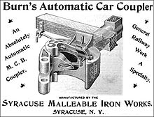


The Janney coupler, later the Master Car Builders Association (MCB) coupler,[17] now the Association of American Railroads (AAR) coupler, is also commonly known as a buckeye, knuckle, or Alliance coupler. The AAR/APTA TypeE, TypeF, and TypeH couplers are all compatible Janney couplers, but used for different rail cars (general freight, tank cars, rotary hoppers, passenger, etc.).
The knuckle coupler or Janney coupler was invented by Eli H. Janney, who received a patent in 1873 (U.S. Patent 138,405).[18] It is also known as a buckeye coupler, notably in the United Kingdom, where some rolling stock (mostly for passenger trains) is fitted with it. Janney was a dry goods clerk and former Confederate Army officer from Alexandria, Virginia, who used his lunch hours to whittle from wood an alternative to the link and pin coupler. The term buckeye comes from the nickname of the US state of Ohio, the "Buckeye State" and the Ohio Brass Company which originally marketed the coupling.[19][20]
In 1893, satisfied that an automatic coupler could meet the demands of commercial railroad operations and, at the same time, be manipulated safely, the United States Congress passed the Safety Appliance Act. Its success in promoting switchyard safety was stunning. Between 1877 and 1887, approximately 38% of all railworker accidents involved coupling. That percentage fell as the railroads began to replace link and pin couplers with automatic couplers. By 1902, only two years after the SAA's effective date, coupling accidents constituted only 4% of all employee accidents. Coupler-related accidents dropped from nearly 11,000 in 1892 to just over 2,000 in 1902, even though the number of railroad employees steadily increased during that decade.
When the Janney coupler was chosen to be the North American standard, there were 8,000 patented alternatives to choose from. The only significant disadvantage of using the Janney design is that sometimes the drawheads need to be manually aligned. Many AAR coupler designs exist to accommodate requirements of various car designs, but all are required to have certain dimensions in common which allow for one design to couple to any other.[21]
The Janney coupler is used in the United States, Canada, Mexico, Japan, India, Taiwan, Australia, New Zealand, South Africa, Saudi Arabia, Cuba, Chile, Brazil, Portugal, China and elsewhere.
The Janney coupler generally provides only mechanical coupling, only Type H adds automatic connections of pneumatic and electrical lines.[22]
Changes since 1873[]
Bazeley coupler[]
Henricot coupler[]


The Henricot coupler is a variation on the Janney coupler, introduced by Belgian engineer and entrepreneur of Court-Saint-Étienne. It is used on certain EMUs of the National Railway Company of Belgium, including the ).
Willison/SA3 coupler[]

An animation of the SA-3 coupler

The Willison coupler was developed in the US in 1916 to address issues present in the Janney coupling.[23]
The Russian SA3 coupler works according to the same principles as the AAR coupler but the two types are incompatible.[24] It was introduced in the Soviet Union in 1932 based on a British patent and has since been used on the whole 1,520 mm (4 ft 11+27⁄32 in) network, including Mongolia. Finnish locomotives have Unilink couplers that can couple to UIC couplers used in Finnish stock and SA3 couplers used in Russian stock.
It is also used on the 1,435 mm (4 ft 8+1⁄2 in) standard gauge networks of Iran and on Malmbanan in Sweden for ore trains. Some 2 ft (610 mm) gauge cane tramway vehicles in Queensland have been fitted with miniature Willison couplers.[25] It was introduced on the 2 ft (610 mm) narrow gauge Avontuur Railway of the South African Railways in 1973.[5]
- Russian trains are rarely longer than about 750 m (2,461 ft)[citation needed] and rarely exceed a maximum tonnage of about 6,000 t (5,900 long tons; 6,600 short tons)[citation needed]. The heaviest trains using these couplers are on Malmbanan where they are up to 9,000 t (8,900 long tons; 9,900 short tons).[26]
- Maximum force the SA3 coupler is able to carry, both tensile and compressive, is about 2.5 MN (280 STf; 250 LTf).[27]
- The maximum allowed tractive effort to the SA-3 is limited to 135 tf (1,320 kN; 133 LTf; 149 STf) (1.32 MN or 300,000 lbf) by Russian white papers.[citation needed]
- The proposed European automatic coupler is compatible with the Russian coupler but with automatic air, control and power connections.[28] Implementation is permanently delayed except for a few users. See Europe below.
- The SA3 resembles a left-handed fist.
The SA3 coupler is one of the strongest couplers in the world – maximum tonnage of a train that uses this type of coupler is about 8000 t[29] – but provides only mechanical coupling.[22] Adding automatic electrical and pneumatic connectivity is a complex challenge.[30]
There are many variations and brand names for these couplers.
As of 2020 CAF is working on an automatic coupler based on SA3, a possible replacement of the buffers and chain coupling on European railways.[31]
Unicoupler/Intermat[]

Unicoupler has been developed by Knorr from West Germany in the 1970s, in parallel with a compatible counterpart, the Intermat coupler, by VEB Waggonbau Bautzen from East Germany.[32][33] The Unicoupler/Intermat coupler can automatically couple two pneumatic lines and up to six electrical connections.[23]
This coupler is mechanically compatible with SA-3 and Willison couplers (but pneumatic and electrical connections must be done manually). The Unicoupler is also known as AK69e.
Maximum tonnage of a train that uses this type of coupler is about 6000 t.[29] AK69e and Intermat adoption failure has been attributed to economic performance.[34]
As of 2020 it has found limited use, it's been adopted by the Iranian Railways[35] and is also used in Germany on trains transporting iron ore between Hamburg and Salzgitter.[36]
C-AKv[]
The C-AKv coupler (also called Transpact) is a newer compact Willison coupler developed by Faiveley Transport.[37] It is mechanically compatible with the SA3 coupler (but pneumatic and electrical connections must be done manually), fully compatible with the Unicoupler and, if additional buffers are mounted, it can be coupled with the conventional European screw coupling as well.[38] The C-AKv coupler can automatically couple two pneumatic lines.[34] As of 2020 its use is limited to trains transporting ore between Rotterdam and Dillingen steelworks and lignite between Wählitz and Buna in Germany.[36]
Z-AK[]
The Z-AK coupler is yet another Willison coupler developed by Knorr Bremse. It was designed in response to the obvious failure of the Unicoupler/Intermat. It is compatible with the buffers and screw coupling. It is one of only few automatic couplers that cannot carry tensile forces, railway vehicles using this type of coupler must be equipped with buffers as well.[39]
Unilink coupler[]
The Unilink coupler is a coupler compatible with SA3 and screw coupling, which is used e.g. in Finland.[40] It is an SA3 coupler with an additional horn that allows hooking up of the chain, and also with an adapter that connects the hook to the SA3 head. Rolling stock equipped with Unilink couplers is also equipped with side buffers.[41]
This section needs expansion. You can help by . (April 2019) |
Multi-function couplers[]
Multi-function couplers (MFCs), or fully automatic couplers, make all connections between the rail vehicles (mechanical, air brake, and electrical) without human intervention, in contrast to autocouplers, or semi-automatic couplers, which just handle the mechanical aspects. The majority of trains fitted with these types of couplers are multiple units, especially those used in mass transit operations.
There are a few designs of fully automatic couplers in use worldwide, including the Scharfenberg coupler, various knuckle hybrids such as the Tightlock (used in the UK), the Wedgelock coupling, Dellner couplings (similar to Scharfenberg couplers in appearance), BSI coupling (Bergische Stahl Industrie, now Faiveley Transport) and the Schaku-Tomlinson Tightlock coupling.
There are a number of other automatic train couplings similar to the Scharfenberg coupler, but not necessarily compatible with it. Older US transit operators continue to use these non-Janney electro-pneumatic coupler designs and have used them for decades.
Westinghouse H2C[]
The Westinghouse H2C coupler, whose predecessor the H2A was first used on the BMT Standards and later the R1 through R9 classes, is currently used on the R32, R42, R62, R62A, R68, and R68A class subway cars of the New York City Subway. The A ends of the cars typically have the Westinghouse coupler and the B ends use either a semi-permanent drawbar, or a Westinghouse coupler.
WABCO N-Type[]

The WABCO N-Type coupler was first developed for the prototype Pittsburgh Skybus system with the initial model N-1 as applied only to the three Skybus cars. The updated model N-2 with a larger 4-inch (101.6 mm) gathering range was first applied to the new "Airporter" rapid transit cars on the Cleveland Rapid Transit line. The model N-2 used lightweight draft gear slung below the center sill, to allow for the wide swings required to go around sharp curves. This made the N-2 unsuitable for main line railroad use so an updated version N-2-A was developed for that market. The first of these were fitted in 1968 to the UAC TurboTrain with 228 electrical contacts and the Budd Metropolitan EMU with 138 contacts. Starting in the 1970s the N-2-A was fitted to the entire SEPTA Silverliner family of MU's, the NJT Arrow series of MU's and the Metro-North Railroad/Long Island Rail Road M series of MU railcars. The N-2 was also used by the PATCO Speedline, but was replaced due to issues with the electrical contacts. Later WABCO would create a new model N-3 for the BART system with a 6-by-4-inch (152.4 mm × 101.6 mm) gathering range which required a rectangular funnel.
The WABCO N-type is sometimes referred to as the pin and cup coupler or spear coupler.
Tomlinson[]


The Tomlinson coupler was developed by the [19][20] for mass transit applications, but eventually found use in some mainline railroad vehicles as well. It consists of two squared metal hooks that engage with each other in a larger rectangular frame with air line connections above and below. Since the coupler's development the manufacturing arm of Ohio Brass was purchased by WABCO which now manufacturers the line along with the N-type. The Tomlinson coupler is the most widely used fully automatic heavy rail coupling in North America having been adopted by the Washington Metro, Massachusetts Bay Transportation Authority, PATCO Speedline, SEPTA Broad Street Subway, Los Angeles Metro Rail, Baltimore Metro, Miami Metro, MARTA Rail and the New York City Subway for its R44/R46 fleet and all modern classes starting with the R142. For applications outside of rapid transit the coupler had to be significantly enlarged to meet the increased strength requirements first appearing in this capacity on the Budd Metroliner and later on the Illinois Central Highliner fleet. Its relative lack of strength is one reason the N-Type has been more successful in the mainline railroad arena.
Outside the United States, the Tomlinson coupler is used on Tokyo Metro's Ginza and Marunouchi Lines[42] and on the heavy capacity Taipei Metro lines.[43]
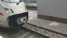
Scharfenberg coupler[]

The Scharfenberg coupler[44] (German: Scharfenbergkupplung or Schaku) is probably the most commonly used type of fully automatic coupling. Designed in 1903 by Karl Scharfenberg in Königsberg, Germany (today Kaliningrad, Russia), it has gradually spread from transit trains to regular passenger service trains, although outside Europe its use is generally restricted to mass transit systems. The Schaku coupler is superior in many ways to many other automatic couplers because it makes the pneumatic and electrical connections automatically and is capable of automatic uncoupling.[45] However, there is no standard for the placement of these electro-pneumatic connections. Some rail companies have them placed on the sides while others have them placed above the mechanical portion of the Schaku coupler.
Small air cylinders, acting on the rotating heads of the coupler, ensure the Schaku coupler engagement, making it unnecessary to use shock to get a good coupling. Joining portions of a passenger train can be done at very low speed (less than 2 mph or 3.2 km/h in the final approach), so that the passengers are not jostled about. Rail equipment manufacturers such as Bombardier offer the Schaku coupler as an option on their mass transit systems and their passenger cars and locomotives. In North America all the trains of the Montreal Metro are equipped with it, as are new light rail systems in Denver, Baltimore and New Jersey. It is also used on light rail vehicles in Portland, Minneapolis, the Vancouver Skytrain, and Line 3 Scarborough in Toronto. It also equips all the dedicated rolling stock used for the shuttle services in the Channel Tunnel.
Maximum tonnage under 1,000 t (1,100 short tons; 980 long tons).
As of 2020 Voith and Dellner are working on an automatic coupler based on Schaku, a possible replacement of the buffers and chain coupling on European railways.[46]
Automatic Buffing Contact coupler[]
- Automatic Buffing Contact (ABC) Coupler[47]
This section needs expansion. You can help by . (February 2019) |
Dellner coupler[]

The Swedish-made Dellner coupling,[48] is a proprietary version of the Scharfenberg coupler, connecting vehicle, pneumatics and electronics at the same time. The patented energy absorption D-BOX technology allows coupling at speeds of up to 15 kilometres per hour (9 mph) with no structural damage, and up to 36 kilometres per hour (22 mph) with deformation but with the vehicles remaining on track. The patented D-REX system provides Ethernet high speed data connection at speeds of 100 Mbit/s.
Ward coupler[]
This section needs expansion. You can help by . (March 2017) |
Ward coupler[49]
Wedgelock coupler[]
This section may require cleanup to meet Wikipedia's quality standards. The specific problem is: this is an incoherent unsourced mess. (December 2019) |

The Wedgelock is the standard coupler on London Underground trains.
The origin of the Wedgelock principle is unclear however there are a number of variants many of which were once produced by The now defunct AEC company in Southall, London. Wedgelock intellectual property was acquired in 1979 by Radenton - later (in 1994) to become Radenton Scharfenberg before both the UK and parent company in Salzgitter were to become part of the Turbo division within Voith. Voith Turbo in Greenford is the designated centre for Wedgelock activity within the Voith group. William Cook Rail are also an OEM for the wedgelock coupling system. Basic design and coupling principle: The older coupler design has a body consisting of two horizontal steel plates separated by shaped blocks to create two pockets - the one on the right (drivers’ perspective) has a vertical pin to anchor a shaped hook protruding forward of a front plate bolted to the body. The second void in the left of the body contains a cylindrical pin with a large flat to create a ‘D-shaped’ cross section. The hook is free to swing left and right through an arc of about 5 degrees and can engage with the D-pin in an opposing coupler. During coupling - once opposing front plates are in contact, a pneumatic actuator within the left hand void drives a (partially) wedge-shaped block behind the outer edge of the opposing hook to engage it with the host D-pin. The sloping ‘wedge‘ geometry occupies central horizontal third of the block and contacts a similar horizontal sloping groove in the opposing hook merely to engage it with the D-pin, the upper and lower thirds of the wedge have pockets machined to create faces parallel to the longitudinal axis of the coupler; as the wedge is caged by body structure it is these faces which prevent sideways movement of the opposing hook and therefore prevent uncoupling. A relatively lightweight spring is enough to maintain the wedge position in the event of a loss of compressed air to the deploy side of the actuator (also known as the wedge-engine). Uncoupling is achieved by air directed to the retract side of the wedge engines on both couplers to retract the wedges and free the hooks; uncoupling is completed by simply moving the vehicles apart. In the event of a loss of ‘retract’ air the wedges can be moved manually to allow uncoupling.
Schwab coupler[]
This section needs expansion. You can help by . (January 2019) |
The Schwab coupler, made by Schwab Verkehrstechnik AG, Schaffhausen, is used on Stadler Kiss and SZU Be 510. It has been offered in four versions:
- Schwab coupler (FK-15-12) for standard gauge trainsets can be found on "Stadler GTW" and "Stadler FLIRT" trainsets of the SBB (GTW and FLIRT), Thurbo (GTW), BLS (GTW), (FLIRT) and SOB (FLIRT).
- Schwab coupler (FK-9-6) for tram and metro trains, among other things
- Schwab coupler (FK-5.5-4 and FK-3-2.5) for narrow gauge railcars
- Schwab coupler (FK-15-10) for standard gauge multiple units are compatible with Scharfenberg type 10
The Schwab coupler is superior in many ways to many other automatic couplers because it makes the pneumatic and electrical connections automatically and is capable of automatic uncoupling.[50]
As of 2020 it is used primarily in Switzerland in regional rail passenger transport.[51]
As of 2020 Wabtec is working on an automatic coupler based on Schwab, a possible replacement of the buffers and chain coupling on European railways.[31]
Shibata coupler[]


The Shibata (or Shibata-type) coupler is a variation of the Scharfenberg coupler which was developed by Japanese Government Railways (JGR) engineer (ja) in the 1930s for electric trains.[note 2] It is the standard coupler type for all passenger trains in Japan as well as on commuter and subway trains in South Korea.
Shinkansen (bullet train) rolling stock utilize a variation of the Shibata coupler developed by Sumitomo Metal Industries in the 1960s which uses rotary tight-lock pins, and which coincidentally bears a closer resemblance to the Scharfenberg coupler rather than the Shibata coupler.[52]
Gallery[]
- Automatic couplers

Scharfenberg coupler
made by Dellner
Scharfenberg coupler
made by Voith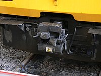
BSI coupler
on British Class 144 DMU
APT Type H Tightlock coupler
on British Rail Class 321
Lower electric connector is not typical in North America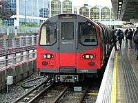
Wedgelock coupler
on London Underground train
WABCO Type N coupler
on SEPTA EMU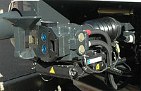
Schwab coupler
on Swiss SBB EMU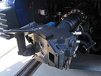
Schwab coupler
on Swiss SBB EMU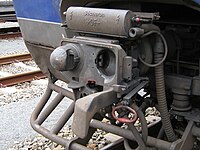
+GF+ Type V coupler
on Belgian EMU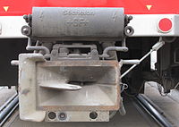
+GF+ Type T
coupler on Prague tram


Dual couplings and match wagons[]

Sometimes a wagon with one coupling system needs to be coupled to wagons with another coupling type This may be needed when taking metro rolling stock from its manufacturer to the city where it is to be used. There are two solutions:
- use a match wagon(s) which has different couplings at either end.
- use a coupling adaptor.
Only some kinds of couplings coexist on the end of a wagon at the same time, because amongst other reasons they need to be at the same height. For example, in the Australian state of Victoria, engines had the AAR coupler, with buffers, and the chain mounted on a lug cast into the AAR coupler.
A match wagon or match truck (also known as a "barrier vehicle" / wagon in Britain and "transition car" in North America) has different kinds of couplings at each end. If a pair of match wagons is used, a rake of wagons using coupling A can be inserted into a train otherwise using coupling B.
A coupling adaptor or compromise coupler might couple to an AAR coupling on a wagon, and present, for example, a meatchopper coupler or rapid transit coupler to the next wagon. Such an adaptor might weigh 100 kg (220 lb). An adapter piece allows a Janney coupler mate with an SA3 coupler[53]
Dual coupling[]
Sets of carriages[]
Automatic couplers like the Janney are safer in a collision because they help prevent the carriages telescoping. British Rail therefore decided to adopt a Janney variant for its passenger carriages, with the coupler able to swing out of the way for coupling to engines with the traditional buffer and chain system.
In New South Wales, sets of carriages were permanently coupled with a fixed bar, since the carriages were disconnected only at the workshops. Freight cars are sometimes coupled in pairs or triplets, using bar couplings in between.
Articulated sets of carriages or wagons share the intermediate bogies, and have no need for couplings in the intermediate positions.
Brake couplings[]
Couplings are needed for any continuous braking systems.
Electronically controlled brakes[]
Electronically controlled pneumatic brakes (ECP) need a method of connecting electrically adjacent wagons, both for power and for command signals, and this can be done by plugs and sockets, or by very short range radio signals.
Draw gear[]
A draw gear (also known as a draft gear) is the assembly behind the coupling at each end of the wagon to take care of the compression and tension forces between the wagons of trains. Early draw gears were made of wood, which was gradually replaced by steel.
Janney couplers have the draft gear in a centersill to absorb the pushing and pulling forces (slack action).[54]
There is also a draw gear behind tightlock couplers, SA3 couplers, C-AKv couplers, Scharfenberg couplers, and other multi-function couplers.
In the case of buffers and chain couplers, the draw gear behind the hooks, if any, will absorb the tension, while the side buffers will absorb the compression.
Some couplers may not have a draw gear.
Model railway couplers[]
On model railroads couplers vary according to scale, and have evolved over many years. Early model trains were coupled using various hook-and-loop arrangements, which were frequently asymmetrical, requiring all cars to be pointing in the same direction. In the larger scales, working scale or near-scale models of Janney couplers were quite common, but proved impractical in HO and smaller scales.
For many years, the "X2F" or "Horn-Hook" coupler was quite common in HO scale, as it could be produced as a single piece of moulded plastic. Similarly, for many years, a "lift-hook" coupler known as the Rapido and developed by Arnold, a German manufacturer of N-scale model trains, was commonly used in that scale.
The chief competitor of both these couplers, more popular among serious modellers, was the Magne-Matic, a magnetically released knuckle coupler developed by Keith and Dale Edwards, and manufactured by Kadee, a company they started. While they closely resemble miniature Janney couplers, they are somewhat different mechanically, with the knuckle pivoting from the center of the coupler head, rather than from the side. A steel pin, designed to resemble an air brake hose, allows the couplers to be released magnetically; the design of the coupler head prevents this from happening unless the train is stopped or reversed with a mated pair of couplers directly over an uncoupling magnet. An earlier, mechanically tripped version of the design had a straight pin extending down from the knuckle itself, which engaged a diamond-shaped mechanical "ramp" between the rails, which had to be raised above rail height when uncoupling was desired.
Once the Kadee patents ran out, a number of other manufacturers began to manufacture similar (and compatible) magnetic knuckle couplers.
Recently, an exact-scale HO model of the AAR coupler has been designed and manufactured by Frank Sergent.[55] This design uses a tiny stainless steel ball to lock the knuckle closed. Uncoupling is achieved by holding a magnetic wand over the coupler pair to draw the balls out of the locking pockets.
In O scale, an exact-scale working miniature version of the "Alliance" coupler was manufactured from the 1980s by GAGO models in Australia. Since 2002 it has been marketed by the Waratah Model Railway Company.[56] European modellers tend to use scale hook and chain couplings.
In British 00 scale (similar to H0 scale) models the 'tension lock' coupler developed by Tri-ang is standard. This is similar in operation to the meatchopper type of coupling. Remote uncoupling is possible by using a sprung ramp between the rails. The design of the hooks is such that the couplings will not uncouple when under tension (instead depressing the ramp). When the train is pushed over the ramp, it will lift the coupling hooks as the train passes over. By halting the train over the ramp, it is split at this point. While it works well, it is often seen as ugly and obtrusive[citation needed] (although smaller designs are available, these are not always fully compatible with other models) and many[citation needed] British modellers prefer to retrofit either Kadee types or working hook and chain couplings.
A recent development is an interchangeable coupling which plugs into a standardised socket, known as NEM 362 and which can be easily unplugged as required. This allows the modeller to easily standardise on whatever coupling is desired, without individual manufacturers needing to change their coupling type.
In 7 mm scale, scale working Norwegian couplings are now being manufactured by Zamzoodled[57] in the UK.
A comparison of coupler types was published in "An introduction to Couplers".[58]
Accidents[]
Different kinds of coupling have different accident rates.
- The Murulla rail accident of 1926 involved the breakage of a "drawhook" leading to a runaway and then a collision. Drawhooks imply "buffers and chain couplers".[59]
- Round Oak rail accident – 1858 – coupling broke and the rear of train rolled back.
See also[]
- Buckeye Steel Castings
- Drawbar
- Gangway connection
- Gender of connectors and fasteners
- Jane's World Railways, lists the coupler(s) used on any railway system
- Railway coupling by country
- Railway coupling conversion
- Slack action
- South Station (Boston), includes a sculpture built of railroad car couplers
Notes[]
- ^ A train with continuous brakes on all wagons.
- ^ From the early 1920s, JGR's EMUs were using Janney couplers, this became a problem because it shocked passengers.[clarification needed] But tightlock coupling didn't exist yet.[citation needed][clarification needed]
References[]
- ^ DAC Report 2020, p. 7.
- ^ Miller Hook
- ^ "Setesdals Railway". Members.ozemail.com.au. Retrieved 2016-04-08.
- ^ Lloyd coupler
- ^ Jump up to: a b c d e f Suid-Afrikaanse Vervoerdienste (South African Transport Services) (1983). Passassierswa- en Trokhandboek (Passenger Carriage and Truck Manual), Vol 1, Hoofstukke 1-15 (Chapters 1-15). South African Transport Services, 1983. Chapter 13.
- ^ George Hart, ed. (1978). The South African Railways - Historical Survey. Bill Hart, Sponsored by Dorbyl Ltd. pp. 9, 11–13.
- ^ Jump up to: a b c Holland, D. F. (1972). Steam Locomotives of the South African Railways. 2: 1910-1955 (1st ed.). Newton Abbott, England: David & Charles. pp. 51–52, 117–118. ISBN 978-0-7153-5427-8.
- ^ Jump up to: a b c Paxton, Leith; Bourne, David (1985). Locomotives of the South African Railways (1st ed.). Cape Town: Struik. pp. 6, 110–112, 156–157. ISBN 0869772112.
- ^ Holland, D.F. (1971). Steam Locomotives of the South African Railways. 1: 1859–1910 (1st ed.). Newton Abbott, England: David & Charles. pp. 84–87, 109–112. ISBN 978-0-7153-5382-0.
- ^ Espitalier, T.J.; Day, W.A.J. (1944). The Locomotive in South Africa - A Brief History of Railway Development. Chapter III - Natal Government Railways. South African Railways and Harbours Magazine, May 1944. pp. 337-340.
- ^ Espitalier, T.J.; Day, W.A.J. (1944). The Locomotive in South Africa - A Brief History of Railway Development. Chapter IV - The N.Z.A.S.M.. South African Railways and Harbours Magazine, October 1944. pp. 762, 764.
- ^ Espitalier, T.J.; Day, W.A.J. (1944). The Locomotive in South Africa - A Brief History of Railway Development. Chapter III - Natal Government Railways (Continued). South African Railways and Harbours Magazine, September 1944. p. 669.
- ^ South African Railways & Harbours/Suid Afrikaanse Spoorweë en Hawens (15 Aug 1941). Locomotive Diagram Book/Lokomotiefdiagramboek, 2′0″ & 3′6″ Gauge/Spoorwydte, Steam Locomotives/Stoomlokomotiewe. SAR/SAS Mechanical Department/Werktuigkundige Dept. Drawing Office/Tekenkantoor, Pretoria. pp. 6a-7a, 25.
- ^ Espitalier, T.J.; Day, W.A.J. (1944). The Locomotive in South Africa - A Brief History of Railway Development. Chapter II - The Cape Government Railways (Continued). South African Railways and Harbours Magazine, April 1944. pp. 253-257.
- ^ Dulez, Jean A. (2012). Railways of Southern Africa 150 Years (Commemorating One Hundred and Fifty Years of Railways on the Sub-Continent – Complete Motive Power Classifications and Famous Trains – 1860–2011) (1st ed.). Garden View, Johannesburg, South Africa: Vidrail Productions. p. 232. ISBN 9 780620 512282.
- ^ DAC Report 2020, p. 13.
- ^ "Internet Archive Search: creator:"Master Car-Builders' Association"". Archive.org. Retrieved 2016-04-08.
- ^ "Eli Janney - The Janney Coupler". Inventors.about.com. Retrieved 2016-04-08.
- ^ Jump up to: a b "Ohio Brass Co. Company Profile on". Aecinfo.com. Retrieved 2016-04-08.
- ^ Jump up to: a b "Ohio Brass Started As Small Jobbing Foundry In 1888" (PDF). Rootsweb.ancestry.com. Retrieved 2016-04-08.
- ^ AAR Manual of Standards and Recommended Practices, Section S, Part III:Coupler and Yoke Details, Issue 06/2007
- ^ Jump up to: a b DAC Report 2020, p. 30–31.
- ^ Jump up to: a b DAC Report 2020, p. 19.
- ^ "ДЖД - Толковый словарь". Railways.id.ru. 2005-05-16. Retrieved 2016-04-08.
- ^ Light Railways, October 2013, p. 23
- ^ Sweden introduces 32.5-tonne axleloads on Iron Ore Line
- ^ DAC Report 2020, p. 22.
- ^ "The SAB WABCO C-AK for goods wagons". Archived from the original on May 19, 2009. Retrieved October 15, 2009.
- ^ Jump up to: a b State of the Art on Automatic Couplers 2017, p. 18.
- ^ DAC Report 2020, p. 20.
- ^ Jump up to: a b DAC Report 2020, p. 5.
- ^ "The Automatic Center Coupler for European Railways". Archived from the original on July 18, 2011. Retrieved November 16, 2010.
- ^ "History of the European Automatic Centre Coupler for Goods Wagons". Archived from the original on October 30, 2007. Retrieved August 3, 2008.
- ^ Jump up to: a b State of the Art on Automatic Couplers 2017, p. 19.
- ^ DAC Report 2020, p. 9.
- ^ Jump up to: a b DAC Report 2020, p. 11.
- ^ "Faiveley Transport Group - Systems and services for the railway industry". Faiveleytransport.com. Retrieved 2016-04-08.
- ^ State of the Art on Automatic Couplers 2017, p. 26.
- ^ State of the Art on Automatic Couplers 2017, pp. 19–20.
- ^ "All purpose couplers: "Willison" type couplers". LAF.
- ^ DAC Report 2020, p. 10.
- ^ "Prototype Couplers". Sumida Crossing.
- ^ OTIS Wang. "臺北捷運C381型高運量電聯車". 雪花台灣.
- ^ "Voith". Voithturbo.de. Retrieved 2016-04-08.
- ^ DAC Report 2020, pp. 26, 30–31.
- ^ DAC Report 2020, pp. 5, 23.
- ^ "ABC Couplers". Archived from the original on May 21, 2009. Retrieved October 4, 2008.
- ^ "Dellner Couplers - Automatic and Semi-Permanent Couplers". Railway Technology. Retrieved 2016-04-08.
- ^ "Coupling, Handing and UNDMs". Trainweb.org. 2002-08-24. Retrieved 2016-04-08.
- ^ DAC Report 2020, pp. 28–29, 30–31.
- ^ DAC Report 2020, p. 26.
- ^ "Prototype Couplers". Sumida Crossing. Retrieved 2016-04-08.
- ^ Adapter piece
- ^ How Does a Draft Gear Absorb Railcar Energy?. YouTube. 8 March 2012. Retrieved 2016-04-08.
- ^ "Sergent Engineering Home Page". Sergentengineering.com. Retrieved 2016-04-08.
- ^ "ModelOKits – Product Information and Online Store". Waratahmrc.com.au. Retrieved 2016-04-08.
- ^ "Zamzoodled home page". Zamzoodled.co.uk. Retrieved 2016-04-08.
- ^ Model Railways in Australia, issue 3, 2009.
- ^ "MURULLA ACCIDENT". The Sydney Morning Herald. National Library of Australia. 23 October 1926. p. 16. Retrieved 17 December 2011.
Sources[]
- Tymczasowe wytyczne obsługi sprzęgu samoczynnego typu UIC/OSŻD, radzieckiego – typu SA3 oraz sprzęgu mieszanego [Interim guidelines for operation of automatic coupler type UIC/OSJD, Soviet—SA3 and adapter] (in Polish). Warsaw: Ministerstwo Komunikacji. 1979.
- Development of Functional Requirements for Sustainable and Attractive European Rail Freight: D5.1 – State of the Art on Automatic Couplers (PDF) (Technical report). Shift2Rail. 3 March 2017.
- Prof. Dr. Markus Hecht, Markus; Mirko Leiste, M.Sc.; Saskia Discher, B.Sc., eds. (29 June 2020). Development of a concept for the EU-wide migration to a digital automatic coupling system (DAC) for rail freight transportation (PDF) (Technical report). Berlin: Berlin University of Technology for the Federal Ministry of Transport and Digital Infrastructure (BMVI).
- Norfolk & Western Railway Co. v. Hiles (95-6), 516 U.S. 400 (1996) (U.S. Supreme Court decision by Justice Clarence Thomas)
- Eli Janney — The Janney Coupler (based on above case)
- Dellner Couplers AB — Automatic and Semi-Permanent Couplers
- Vancouver SkyTrain Light Rail Network, Canada (these two for Dellner data)
- JANE'S WORLD RAILWAYS
- How couplings work
- White, John H. (1985) [1978]. The American Railroad Passenger Car. Baltimore, Maryland: Johns Hopkins University Press. ISBN 978-0-8018-2743-3.
External links[]
| Wikimedia Commons has media related to Coupling systems of rail vehicles. |
| show Authority control |
|---|
- Locomotive parts
- Couplers