Haber process
The Haber process,[1] also called the Haber–Bosch process, is an artificial nitrogen fixation process and is the main industrial procedure for the production of ammonia today.[2][3] It is named after its inventors, the German chemists Fritz Haber and Carl Bosch, who developed it in the first decade of the 20th century. The process converts atmospheric nitrogen (N2) to ammonia (NH3) by a reaction with hydrogen (H2) using a metal catalyst under high temperatures and pressures:

Before the development of the Haber process, ammonia had been difficult to produce on an industrial scale,[4][5][6] with early methods such as the Birkeland–Eyde process and Frank–Caro process all being highly inefficient.
Although the Haber process is mainly used to produce fertilizer today, during World War I it provided Germany with a source of ammonia for the production of explosives, compensating for the Allied Powers' trade blockade on Chilean saltpeter.
History[]
Throughout the 19th century the demand for nitrates and ammonia for use as fertilizers and industrial feedstocks had been steadily increasing. The main source was mining niter deposits and guano from tropical islands.[7] At the beginning of the 20th century it was being predicted that these reserves could not satisfy future demands,[8] and research into new potential sources of ammonia became more important. Although atmospheric nitrogen (N2) is abundant, comprising nearly 80% of the air, it is exceptionally stable and does not readily react with other chemicals. Converting N2 into ammonia posed a challenge for chemists globally.
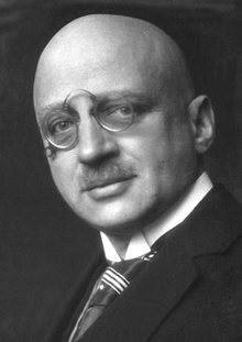
Haber, with his assistant Robert Le Rossignol, developed the high-pressure devices and catalysts needed to demonstrate the Haber process at laboratory scale.[9][10] They demonstrated their process in the summer of 1909 by producing ammonia from air, drop by drop, at the rate of about 125 mL (4 US fl oz) per hour. The process was purchased by the German chemical company BASF, which assigned Carl Bosch the task of scaling up Haber's tabletop machine to industrial-level production.[5][11] He succeeded in 1910. Haber and Bosch were later awarded Nobel prizes, in 1918 and 1931 respectively, for their work in overcoming the chemical and engineering problems of large-scale, continuous-flow, high-pressure technology.[5]
Ammonia was first manufactured using the Haber process on an industrial scale in 1913 in BASF's Oppau plant in Germany, reaching 20 tonnes per day the following year.[12] During World War I, the production of munitions required large amounts of nitrate. The Allies had access to large deposits of sodium nitrate in Chile (Chile saltpetre) controlled by British companies. Germany had no such resources, so the Haber process proved essential to the German war effort.[5][13] Synthetic ammonia from the Haber process was used for the production of nitric acid, a precursor to the nitrates used in explosives.
Today, the most popular catalysts are based on iron promoted with K2O, CaO, SiO2, and Al2O3. Earlier, molybdenum was also used as a promoter. The original Haber–Bosch reaction chambers used osmium as the catalyst, but it was available in extremely small quantities. Haber noted uranium was almost as effective and easier to obtain than osmium. Under Bosch's direction in 1909, the BASF researcher Alwin Mittasch discovered a much less expensive iron-based catalyst, which is still used today. A major contributor to the elucidation of this catalysis was Gerhard Ertl.[14][15][16][17]
During the interwar years, alternative processes were developed, the most notably different being the Casale process and Claude process. Luigi Casale and Georges Claude proposed to increase the pressure of the synthesis loop to 80–100 MPa (800–1,000 bar; 12,000–15,000 psi), thereby increasing the single-pass ammonia conversion and making nearly complete liquefaction at ambient temperature feasible. Georges Claude even proposed to have three or four converters with liquefaction steps in series, thereby omitting the need for a recycle. Nowadays, most plants resemble the original Haber process (20 MPa (200 bar; 2,900 psi) and 500 °C (932 °F)), albeit with improved single-pass conversion and lower energy consumption due to process and catalyst optimization.
Process[]

This conversion is typically conducted at pressures above 10 MPa (100 bar; 1,450 psi) and between 400 and 500 °C (752 and 932 °F), as the gases (nitrogen and hydrogen) are passed over four beds of catalyst, with cooling between each pass for maintaining a reasonable equilibrium constant. On each pass only about 15% conversion occurs, but any unreacted gases are recycled, and eventually an overall conversion of 97% is achieved.[3]
The steam reforming, shift conversion, carbon dioxide removal, and methanation steps each operate at pressures of about 2.5–3.5 MPa (25–35 bar; 360–510 psi), and the ammonia synthesis loop operates at pressures ranging from 6 to 18 MPa (60 to 180 bar; 870 to 2,610 psi), depending upon which proprietary process is used.[3]
Sources of hydrogen[]
The major source of hydrogen is methane from natural gas. The conversion, steam reforming, is conducted with steam in a high-temperature and -pressure tube inside a reformer with a nickel catalyst, separating the carbon and hydrogen atoms in the natural gas. Other fossil fuel sources include coal, heavy fuel oil and naphtha, while hydrogen is also produced from biomass and from electrolysis of water.
Reaction rate and equilibrium[]
Nitrogen gas (N2) is very unreactive because the atoms are held together by strong triple bonds. The Haber process relies on catalysts that accelerate the scission of this triple bond.
Two opposing considerations are relevant to this synthesis: the position of the equilibrium and the rate of reaction. At room temperature, the equilibrium is strongly in favor of ammonia, but the reaction doesn't proceed at a detectable rate due to its high activation energy. Because the reaction is exothermic, the equilibrium constant becomes 1 around 150–200 °C (302–392 °F) (see Le Châtelier's principle).[3]
| Temperature (°C) | Kp |
|---|---|
| 300 | 4.34 × 10⁻³ |
| 400 | 1.64 × 10⁻⁴ |
| 450 | 4.51 × 10⁻⁵ |
| 500 | 1.45 × 10⁻⁵ |
| 550 | 5.38 × 10⁻⁶ |
| 600 | 2.25 × 10⁻⁶ |
Above this temperature, the equilibrium quickly becomes quite unfavorable for the reaction product at atmospheric pressure, according to the van 't Hoff equation. Lowering the temperature is also unhelpful because the catalyst requires a temperature of at least 400 °C to be efficient.[3]
Increased pressure does favor the forward reaction because there are 4 moles of reactant for every 2 moles of product, and the pressure used (15–25 MPa (150–250 bar; 2,200–3,600 psi)) alters the equilibrium concentrations to give a substantial ammonia yield. The reason for this is evident in the equilibrium relationship, which is

where is the fugacity coefficient of species , is the mole fraction of the same species, is the pressure in the reactor, and is standard pressure, typically 1 bar (0.10 MPa).


Economically, pressurization of the reactor is expensive: pipes, valves, and reaction vessels need to be strengthened, and there are safety considerations when working at 20 MPa. In addition, running compressors takes considerable energy, as work must be done on the (very compressible) gas. Thus, the compromise used gives a single-pass yield of around 15%[3]
While removing the product (i.e., ammonia gas) from the system would increase the reaction yield, this step is not used in practice, since the temperature is too high; it is removed from the equilibrium mixture of gases leaving the reaction vessel. The hot gases are cooled enough, whilst maintaining a high pressure, for the ammonia to condense and be removed as liquid. Unreacted hydrogen and nitrogen gases are then returned to the reaction vessel to undergo further reaction.[3] While most ammonia is removed (typically down to 2–5 mol.%), some ammonia remains in the recycle stream to the converter. In academic literature, more complete separation of ammonia has been proposed by absorption in metal halides and by adsorption on zeolites. Such a process is called a absorbent-enhanced Haber process or adsorbent-enhanced Haber-Bosch process.
Catalysts[]


The Haber–Bosch process relies on catalysts to accelerate the hydrogenation of N2. The catalysts are "heterogeneous", meaning that they are solid that interact on gaseous reagents.[19]
The catalyst typically consists of finely divided iron bound to an iron oxide carrier containing promoters possibly including aluminium oxide, potassium oxide, calcium oxide, potassium hydroxide,[20] molybdenum,[21] and magnesium oxide.
Production of iron-based catalysts[]
In industrial practice, the iron catalyst is obtained from finely ground iron powder, which is usually obtained by reduction of high-purity magnetite (Fe3O4). The pulverized iron metal is burnt (oxidized) to give magnetite or wüstite (FeO, ferrous oxide) of a defined particle size. The magnetite (or wüstite) particles are then partially reduced, removing some of the oxygen in the process. The resulting catalyst particles consist of a core of magnetite, encased in a shell of wüstite, which in turn is surrounded by an outer shell of iron metal. The catalyst maintains most of its bulk volume during the reduction, resulting in a highly porous high-surface-area material, which enhances its effectiveness as a catalyst. Other minor components of the catalyst include calcium and aluminium oxides, which support the iron catalyst and help it maintain its surface area. These oxides of Ca, Al, K, and Si are unreactive to reduction by the hydrogen.[3]
The production of the required magnetite catalyst requires a particular melting process in which the used raw materials must be free of catalyst poisons and the promoter aggregates must be evenly distributed in the magnetite melt. Rapid cooling of the magnetite melt, which has an initial temperature of about 3500 °C, produces the precursor desired highly active catalyst. Unfortunately, the rapid cooling ultimately forms a catalyst of reduced abrasion resistance. Despite this disadvantage, the method of rapid cooling is often preferred in practice.[3]
The reduction of the catalyst precursor magnetite to α-iron is carried out directly in the production plant with synthesis gas. The reduction of the magnetite proceeds via the formation of wüstite (FeO), so that particles with a core of magnetite surrounded by a shell of wüstite are formed. The further reduction of magnetite and wüstite leads to the formation of α-iron, which forms together with the promoters the outer shell.[22] The involved processes are complex and depend on the reduction temperature: At lower temperatures, wüstite disproportionates into an iron phase and a magnetite phase; at higher temperatures, the reduction of the wüstite and magnetite to iron dominates.[23]
The α-iron forms primary crystallites with a diameter of about 30 nanometers. These form crystallites a bimodal pore system with pore diameters of about 10 nanometers (produced by the reduction of the magnetite phase) and of 25 to 50 nanometers (produced by the reduction of the wüstite phase).[22] With the exception of cobalt oxide, the promoters are not reduced.
During the reduction of the iron oxide with synthesis gas, water vapour is formed. This water vapor must be considered for high catalyst quality as contact with the finely divided iron would lead to premature aging of the catalyst through recrystallization, especially in conjunction with high temperatures. The vapour pressure of the water in the gas mixture produced during catalyst formation is thus kept as low as possible, target values are below 3 gm−3. For this reason, the reduction is carried out at high gas exchange, low pressure and low temperatures. The exothermic nature of the ammonia formation ensures a gradual increase in temperature.[3]
The reduction of fresh, fully oxidized catalyst or precursor to full production capacity takes four to ten days.[3] The wüstite phase is reduced faster and at lower temperatures than the magnetite phase (Fe3O4). After detailed kinetic, microscopic and X-ray spectroscopic investigations it was shown that wüstite reacts first to metallic iron. This leads to a gradient of iron(II) ions, whereby these diffuse from the magnetite through the wüstite to the particle surface and precipitate there as iron nuclei.
In industrial practice, pre-reduced, stabilised catalysts have gained a significant market share. They are delivered showing the fully developed pore structure, but have been oxidized again on the surface after manufacture and are therefore no longer pyrophoric. The reactivation of such pre-reduced catalysts requires only 30 to 40 hours instead of the usual time periods of several days. In addition to the short start-up time, they also have other advantages such as higher water resistance and lower weight.[3]
| Typical catalyst composition[24] | % iron | % potassium | % aluminium | % calcium | % oxygen |
|---|---|---|---|---|---|
| volume composition | 40.5 | 0.35 | 2.0 | 1.7 | 53.2 |
| Surface composition before reduction | 8.6 | 36.1 | 10.7 | 4.7 | 40.0 |
| Surface composition after reduction | 11.0 | 27.0 | 17.0 | 4.0 | 41.0 |
Catalysts other than iron[]
Since the industrial launch of the Haber–Bosch process, many efforts have been made to improve it. Many metals were intensively tested in the search for suitable catalysts: The requirement for suitability is the dissociative adsorption of nitrogen (i. e. the nitrogen molecule must be split upon adsorption into nitrogen atoms). At the same time the binding of the nitrogen atoms must not be too strong, otherwise the catalyst would be blocked and the catalytic ability would be reduced (i. e. self-poisoning). The elements in the periodic table at the left of the iron group show such a strong bond to nitrogen. The formation of surface nitrides makes for example chromium catalysts ineffective. Metals to the right of the iron group, in contrast, adsorb nitrogen too weakly to be able to activate it sufficiently for ammonia synthesis. Haber initially used catalysts based on osmium and uranium. Uranium reacts to its nitride during catalysis and osmium oxide is rare.[25]
Due to the comparatively low price, high availability, easy processing, lifespan and activity, iron was ultimately chosen as catalyst. The production of 1800 tons ammonia per day requires a gas pressure of at least 130 bar, temperatures of 400 to 500 °C and a reactor volume of at least 100 m³. According to theoretical and practical studies, further improvements of the pure iron catalyst are limited. In 1984 it was noticed that the activity of iron catalysts were increased by inclusion of cobalt.
Second generation catalysts[]
Ruthenium forms highly active catalysts. Allowing milder operating pressures and temperatures, Ru-based materials are referred to as second-generation catalysts. Such catalysts are prepared by decomposition of triruthenium dodecacarbonyl on graphite.[3] A drawback of activated-carbon-supported ruthenium-based catalysts is the methanation of the support in the presence of hydrogen. Their activity is strongly dependent on the catalyst carrier and the promoters. A wide range of substances can be used as carriers, including carbon, magnesium oxide, aluminum oxide, zeolites, spinels, and boron nitride.[26]
Ruthenium-activated carbon-based catalysts have been used industrially in the KBR Advanced Ammonia Process (KAAP) since 1992.[27] The carbon carrier is partially degraded to methane; however, this can be mitigated by a special treatment of the carbon at 1500 °C, thus prolonging the catalysts lifetime. In addition, the finely dispersed carbon poses a risk of explosion. For these reasons and due to its low acidity, magnesium oxide has proven to be a good alternative. Carriers with acidic properties extract electrons from ruthenium, make it less reactive, and undesirably bind ammonia to the surface.[26]
Catalyst poisons[]
Catalyst poisons lower the activity of the catalyst. They are usually impurities in the synthesis gas (a raw material). Sulfur compounds, phosphorus compounds, arsenic compounds, and chlorine compounds are permanent catalyst poisons. Water, carbon monoxide, carbon dioxide and oxygen are temporary catalyst poisons.[3]
Although chemically inert components of the synthesis gas mixture such as noble gases or methane are not catalyst poisons in the strict sense, they accumulate through the recycling of the process gases and thus lower the partial pressure of the reactants, which in turn has a negative effect on the conversion.[28]
Industrial production[]
Synthesis parameters[]
| temperature (°C) | Keq |
|---|---|
| 300 | 4.34 × 10⁻³ |
| 400 | 1.64 × 10⁻⁴ |
| 450 | 4.51 × 10⁻⁵ |
| 500 | 1.45 × 10⁻⁵ |
| 550 | 5.38 × 10⁻⁶ |
| 600 | 2.25 × 10⁻⁶ |
The formation of ammonia occurs from nitrogen and hydrogen according to the following equation:

The reaction is an exothermic equilibrium reaction in which the gas volume is reduced. The equilibrium constant Keq of the reaction (see table) is obtained from the following equation:

Since the reaction is exothermic, the equilibrium of the reaction shifts at lower temperatures to the side of the ammonia. Furthermore, four volumetric parts of the raw materials produce two volumetric parts of ammonia. According to Le Chatelier's principle, a high pressure therefore also favours the formation of ammonia. In addition, a high pressure is necessary to ensure sufficient surface coverage of the catalyst with nitrogen.[31] For this reason, a ratio of nitrogen to hydrogen of 1 to 3, a pressure of 250 to 350 bar, a temperature of 450 to 550 °C and α iron are used as catalysts.
The catalyst ferrite (α-Fe) is produced in the reactor by the reduction of magnetite with hydrogen. The catalyst has its highest efficiency at temperatures of about 400 to 500 °C. Even though the catalyst greatly lowers the activation energy for the cleavage of the triple bond of the nitrogen molecule, high temperatures are still required for an appropriate reaction rate. At the industrially utilized reaction temperature of 450 to 550 °C an optimum between the decomposition of ammonia into the starting materials and the effectiveness of the catalyst is achieved.[32] The formed ammonia is continuously removed from the system. The volume fraction of ammonia in the gas mixture is about 20%.
The inert components, especially the noble gases such as argon, should not exceed a certain content in order not to reduce the partial pressure of the reactants too much. To remove the inert gas components, part of the gas is removed and the argon is separated in a gas separation plant. The extraction of pure argon from the circulating gas is carried out using the Linde process.[33]
Large-scale technical implementation[]
Modern ammonia plants produce more than 3000 tons per day in one production line. The following diagram shows the set-up of a Haber–Bosch plant:

Depending on its origin, the synthesis gas must first be freed from impurities such as hydrogen sulphide or organic sulphur compounds, which act as a catalyst poison. High concentrations of hydrogen sulphide, which occur in synthesis gas from carbonization coke, are removed in a wet cleaning stage such as the , while low concentrations are removed by adsorption on activated carbon.[34] Organosulfur compounds are separated by pressure swing adsorption together with carbon dioxide after CO conversion.
To produce hydrogen by steam reforming, methane reacts with water vapor using a nickel oxide-alumina catalyst in the primary reformer to form carbon monoxide and hydrogen. The energy required for this, the enthalpy ΔH, is 206 kJ/mol.[35]

The methane gas reacts in the primary reformer only partially. In order to increase the hydrogen yield and keep the content of inert components (i. e. methane) as low as possible, the remaining methane gas is converted in a second step with oxygen to hydrogen and carbon monoxide in the secondary reformer. The secondary reformer is supplied with air as oxygen source. Also the required nitrogen for the subsequent ammonia synthesis is added to the gas mixture.

In a third step, the carbon monoxide is oxidized to carbon dioxide, which is called CO conversion or water-gas shift reaction.

Carbon monoxide and carbon dioxide would form carbamates with ammonia, which would clog (as solids) pipelines and apparatus within a short time. In the following process step, the carbon dioxide must therefore be removed from the gas mixture. In contrast to carbon monoxide, carbon dioxide can easily be removed from the gas mixture by gas scrubbing with triethanolamine. The gas mixture then still contains methane and noble gases such as argon, which, however, behave inertly.[28]
The gas mixture is then compressed to operating pressure by turbo compressors. The resulting compression heat is dissipated by heat exchangers; it is used to preheat raw gases.
The actual production of ammonia takes place in the ammonia reactor. The first reactors were bursting under the high pressure because the atomic hydrogen in the carbonaceous steel partially recombined to methane and produced cracks in the steel. Bosch therefore developed tube reactors consisting of a pressure-bearing steel tube in which a low-carbon iron lining tube was inserted filled with the catalyst. Hydrogen that diffused through the inner steel pipe escaped to the outside via thin holes in the outer steel jacket, the so-called Bosch holes.[30] A disadvantage of the tubular reactors was the relatively high pressure loss, which had to be applied again by compression. The development of hydrogen-resistant chromium-molybdenum steels made it possible to construct single-walled pipes.[36]

Modern ammonia reactors are designed as multi-storey reactors with low pressure drop, in which the catalysts are distributed as fills over about ten storeys one above the other. The gas mixture flows through them one after the other from top to bottom. Cold gas is injected from the side for cooling. A disadvantage of this reactor type is the incomplete conversion of the cold gas mixture in the last catalyst bed.[36]
Alternatively, the reaction mixture between the catalyst layers is cooled using heat exchangers, whereby the hydrogen-nitrogen mixture is preheated to reaction temperature. Reactors of this type have three catalyst beds. In addition to good temperature control, this reactor type has the advantage of better conversion of the raw material gases compared to reactors with cold gas injection.
The reaction product is continuously removed for maximum yield. The gas mixture is cooled to 450 °C in a heat exchanger using water, freshly supplied gases and other process streams. The ammonia also condenses and is separated in a pressure separator. Unreacted nitrogen and hydrogen are than compressed back to the process by a circulating gas compressor, supplemented with fresh gas and fed to the reactor.[36] In a subsequent distillation, the product ammonia is purified.
Mechanism[]
Elementary steps[]
The mechanism of ammonia synthesis contains the following seven elementary steps:
- transport of the reactants from the gas phase through the boundary layer to the surface of the catalyst.
- pore diffusion to the reaction center
- adsorption of reactants
- reaction
- desorption of product
- transport of the product through the pore system back to the surface
- transport of the product into the gas phase
Transport and diffusion (the first and last two steps) are fast compared to adsorption, reaction and desorption because of the shell structure of the catalyst. It is known from various investigations that the rate-determining step of the ammonia synthesis is the dissociation of nitrogen.[3] In contrast, exchange reactions between hydrogen and deuterium on the Haber–Bosch catalysts still take place at temperatures of −196 °C (−320.8 °F) at a measurable rate; the exchange between deuterium and hydrogen on the ammonia molecule also takes place at room temperature. Since the adsorption of both molecules is rapid, it cannot determine the speed of ammonia synthesis.[37]
In addition to the reaction conditions, the adsorption of nitrogen on the catalyst surface depends on the microscopic structure of the catalyst surface. Iron has different crystal surfaces, whose reactivity is very different. The Fe(111) and Fe(211) surfaces have by far the highest activity. The explanation for this is that only these surfaces have so-called C7 sites - these are iron atoms with seven closest neighbours.[3]
The dissociative adsorption of nitrogen on the surface follows the following scheme, where S* symbolizes an iron atom on the surface of the catalyst:[22]
- N2 → S*–N2 (γ-species) → S*–N2–S* (α-species) → 2 S*–N (β-species, surface nitride)
The adsorption of nitrogen is similar to the chemisorption of carbon monoxide. On a Fe(111) surface, the adsorption of nitrogen first leads to an adsorbed γ-species with an adsorption energy of 24 kJmol−1 and an N-N stretch vibration of 2100 cm−1. Since the nitrogen is isoelectronic to carbon monoxide, it adsorbs in an on-end configuration in which the molecule is bound perpendicular to the metal surface at one nitrogen atom.[16][38][3] This has been confirmed by photoelectron spectroscopy.[39]
Ab-initio-MO calculations have shown that, in addition to the σ binding of the free electron pair of nitrogen to the metal, there is a π binding from the d orbitals of the metal to the π* orbitals of nitrogen, which strengthens the iron-nitrogen bond. The nitrogen in the α state is more strongly bound with 31 kJmol−1. The resulting N-N bond weakening could be experimentally confirmed by a reduction of the wave numbers of the N-N stretching oscillation to 1490 cm−1.[38]
Further heating of the Fe(111) area covered by α-N2 leads to both desorption and emergence of a new band at 450 cm−1. This represents a metal-nitrogen oscillation, the β state. A comparison with vibration spectra of complex compounds allows the conclusion that the N2 molecule is bound "side-on", with an N atom in contact with a C7 site. This structure is called "surface nitride". The surface nitride is very strongly bound to the surface.[39] Hydrogen atoms (Hads), which are very mobile on the catalyst surface, quickly combine with it.
Infrared spectroscopically detected surface imides (NHad), surface amides (NH2,ad) and surface ammoniacates (NH3,ad) are formed, the latter decay under NH3 release (desorption).[30] The individual molecules were identified or assigned by X-ray photoelectron spectroscopy (XPS), high-resolution electron energy loss spectroscopy (HREELS) and IR spectroscopy.
 Drawn reaction scheme

On the basis of these experimental findings, the reaction mechanism is believed to involve the following steps (see also figure):[40]
- N2 (g) → N2 (adsorbed)
- N2 (adsorbed) → 2 N (adsorbed)
- H2 (g) → H2 (adsorbed)
- H2 (adsorbed) → 2 H (adsorbed)
- N (adsorbed) + 3 H (adsorbed) → NH3 (adsorbed)
- NH3 (adsorbed) → NH3 (g)
Reaction 5 occurs in three steps, forming NH, NH2, and then NH3. Experimental evidence points to reaction 2 as being the slow, rate-determining step. This is not unexpected, since the bond broken, the nitrogen triple bond, is the strongest of the bonds that must be broken.
As with all Haber–Bosch catalysts, nitrogen dissociation is the rate determining step for ruthenium activated carbon catalysts. The active center for ruthenium is a so-called B5 site, a 5-fold coordinated position on the Ru(0001) surface where two ruthenium atoms form a step edge with three ruthenium atoms on the Ru(0001) surface.[41] The number of B5 sites depends on the size and shape of the ruthenium particles, the ruthenium precursor and the amount of ruthenium used.[26] The reinforcing effect of the basic carrier used in the ruthenium catalyst is similar to the promoter effect of alkali metals used in the iron catalyst.[26]
Energy diagram[]

An energy diagram can be created based on the enthalpy of reaction of the individual steps. The energy diagram can be used to compare homogeneous and heterogeneous reactions: Due to the high activation energy of the dissociation of nitrogen, the homogeneous gas phase reaction is not realizable. The catalyst avoids this problem as the energy gain resulting from the binding of nitrogen atoms to the catalyst surface overcompensates for the necessary dissociation energy so that the reaction is finally exothermic. Nevertheless, the dissociative adsorption of nitrogen remains the rate determining step: not because of the activation energy, but mainly because of the unfavorable pre-exponential factor of the rate constant. Although hydrogenation is endothermic, this energy can easily be applied by the reaction temperature (about 700 K).[3]
Economic and environmental aspects[]

When first invented, the Haber process competed against another industrial process, the cyanamide process. However, the cyanamide process consumed large amounts of electrical power and was more labor-intensive than the Haber process.[5]: 137–143
As of 2018, the Haber process produces 230 million tonnes of anhydrous ammonia per year.[42] The ammonia is used mainly as a nitrogen fertilizer as ammonia itself, in the form of ammonium nitrate, and as urea. The Haber process consumes 3–5% of the world's natural-gas production (around 1–2% of the world's energy supply).[4][43][44][45] In combination with advances in breeding, herbicides and pesticides, these fertilizers have helped to increase the productivity of agricultural land:
With average crop yields remaining at the 1900 level[,] the crop harvest in the year 2000 would have required nearly four times more land[,] and the cultivated area would have claimed nearly half of all ice-free continents, rather than under 15% of the total land area that is required today.[46]
The energy-intensivity of the process contributes to climate change and other environmental problems:
leaching of nitrates into ground water, rivers, ponds and lakes; expanding dead zones in coastal ocean waters, resulting from recurrent eutrophication; atmospheric deposition of nitrates and ammonia affecting natural ecosystems; higher emissions of nitrous oxide (N2O), now the third most important greenhouse gas following CO2 and CH4.[46]
The Haber–Bosch process is one of the largest contributors to a buildup of reactive nitrogen in the biosphere, causing an anthropogenic disruption to the nitrogen cycle.[47]
Since nitrogen use efficiency is typically less than 50%,[48] farm runoff from heavy use of fixed industrial nitrogen disrupts biological habitats.[4][49]
Nearly 50% of the nitrogen found in human tissues originated from the Haber–Bosch process.[50] Thus, the Haber process serves as the "detonator of the population explosion", enabling the global population to increase from 1.6 billion in 1900 to 7.7 billion by November 2018.[51]
See also[]
- Other nitrogen fixation processes
- Birkeland-Eyde process
- Cyanamide process
- Other contemporary nitrogen sources
- Guano
- Chilean saltpeter
- Hydrogen production
- Industrial gas
- Paradas method
References[]
- ^ Papers, Chemistry (2018). Habers process chemistry. India: Arihant publications. p. 264. ISBN 9789313163039.
- ^ Appl, M. (1982). "The Haber–Bosch Process and the Development of Chemical Engineering". A Century of Chemical Engineering. New York: Plenum Press. pp. 29–54. ISBN 978-0-306-40895-3.
- ^ Jump up to: a b c d e f g h i j k l m n o p q r Appl, Max (2006). "Ammonia". Ullmann's Encyclopedia of Industrial Chemistry. Weinheim: Wiley-VCH. doi:10.1002/14356007.a02_143.pub2.
- ^ Jump up to: a b c Smil, Vaclav (2004). Enriching the Earth: Fritz Haber, Carl Bosch, and the Transformation of World Food Production (1st ed.). Cambridge, MA: MIT. ISBN 9780262693134.
- ^ Jump up to: a b c d e Hager, Thomas (2008). The Alchemy of Air: A Jewish genius, a doomed tycoon, and the scientific discovery that fed the world but fueled the rise of Hitler (1st ed.). New York, NY: Harmony Books. ISBN 978-0-307-35178-4.
- ^ Sittig, Marshall (1979). Fertilizer Industry: Processes, Pollution Control, and Energy Conservation. Park Ridge, NJ: Noyes Data Corp. ISBN 978-0-8155-0734-5.
- ^ Vandermeer, John (2011). The Ecology of Agroecosystems. Jones & Bartlett Learning. p. 149. ISBN 978-0-7637-7153-9.
- ^ James, Laylin K. (1993). Nobel Laureates in Chemistry 1901–1992 (3rd ed.). Washington, DC: American Chemical Society. p. 118. ISBN 978-0-8412-2690-6.
- ^ Haber, Fritz (1905). Thermodynamik technischer Gasreaktionen (in German) (1st ed.). Paderborn: Salzwasser Verlag. ISBN 9783864448423.
- ^ "Robert Le Rossignol, 1884–1976: Professional Chemist" (PDF), ChemUCL Newsletter: 8, 2009, archived from the original (PDF) on 13 January 2011.
- ^ Bosch, Carl (2 March 1908) "Process of producing ammonia." U.S. Patent 990,191.
- ^ Philip, Phylis Morrison (2001). "Fertile Minds (Book Review of Enriching the Earth: Fritz Haber, Carl Bosch, and the Transformation of World Food Production)". American Scientist. Archived from the original on 2 July 2012.
- ^ "Nobel Award to Haber" (PDF). The New York Times. 3 February 1920. Archived from the original (PDF) on 24 February 2021. Retrieved 11 October 2010.
- ^ Bozso, F.; Ertl, G.; Grunze, M.; Weiss, M. (1977). "Interaction of nitrogen with iron surfaces: I. Fe(100) and Fe(111)". Journal of Catalysis. 49 (1): 18–41. doi:10.1016/0021-9517(77)90237-8.
- ^ Imbihl, R.; Behm, R. J.; Ertl, G.; Moritz, W. (1982). "The structure of atomic nitrogen adsorbed on Fe(100)" (PDF). Surface Science. 123 (1): 129–140. Bibcode:1982SurSc.123..129I. doi:10.1016/0039-6028(82)90135-2.
- ^ Jump up to: a b Ertl, G.; Lee, S. B.; Weiss, M. (1982). "Kinetics of nitrogen adsorption on Fe(111)". Surface Science. 114 (2–3): 515–526. Bibcode:1982SurSc.114..515E. doi:10.1016/0039-6028(82)90702-6.
- ^ Ertl, G. (1983). "Primary steps in catalytic synthesis of ammonia". J. Vac. Sci. Technol. A. 1 (2): 1247–1253. Bibcode:1983JVSTA...1.1247E. doi:10.1116/1.572299.
- ^ Brown, Theodore L.; LeMay, H. Eugene, Jr.; Bursten, Bruce E. (2006). "Table 15.2". Chemistry: The Central Science (10th ed.). Upper Saddle River, NJ: Pearson. ISBN 978-0-13-109686-8.
- ^ Alwin Mittasch (1926). "Bemerkungen zur Katalyse". Berichte der Deutschen Chemischen Gesellschaft (A and B Series). 59: 13–36. doi:10.1002/cber.19260590103.
- ^ "3.1 Ammonia synthesis". resources.schoolscience.co.uk. Archived from the original on 6 July 2020.
- ^ Rock, Peter A. (19 June 2013). Chemical Thermodynamics. p. 317. ISBN 9781891389320.
- ^ Jump up to: a b c Max Appl (2006). "Ammonia". Ullmann's Encyclopedia of Industrial Chemistry. Weinheim: Wiley-VCH. doi:10.1002/14356007.a02_143.pub2.
- ^ W. K. Jozwiak; E. Kaczmarek (2007). "Reduction behavior of iron oxides in hydrogen and carbon monoxide atmospheres". Applied Catalysis A: General. 326: 17–27. doi:10.1016/j.apcata.2007.03.021.
- ^ Gerhard Ertl (1983). "Zum Mechanismus der Ammoniak-Synthese". Nachrichten aus Chemie, Technik und Laboratorium. 31 (3): 178–182. doi:10.1002/nadc.19830310307.
- ^ Michael Bowker (1993). "Chapter 7". In D. A. King; D. P. Woodruff (eds.). The Chemical Physics of Solid Surfaces. Volume 6: Coadsorption, promoters and poisons. Elsevier. pp. 225–268. ISBN 0-444-81468-X.
|volume=has extra text (help) - ^ Jump up to: a b c d Zhixiong You; Koji Inazu; Ken-ichi Aika; Toshihide Baba (October 2007). "Electronic and structural promotion of barium hexaaluminate as a ruthenium catalyst support for ammonia synthesis". Journal of Catalysis. 251 (2): 321–331. doi:10.1016/j.jcat.2007.08.006.
- ^ F. Rosowski; A. Hornung; O. Hinrichsen; D. Herein; M. Muhler (April 1997). "Ruthenium catalysts for ammonia synthesis at high pressures: Preparation, characterization, and power-law kinetics". Applied Catalysis A: General. 151 (2): 443–460. doi:10.1016/S0926-860X(96)00304-3.
- ^ Jump up to: a b Jürgen Falbe (1997). Römpp-Lexikon Chemie (H–L). Georg Thieme Verlag. pp. 1644–1646. ISBN 3-13-107830-8.
- ^ Theodore L. Brown; H. Eugene LeMay; Bruce Edward Bursten (2003). Linda Sue Brunauer (ed.). Chemistry the Central Science (9th ed.). Upper Saddle River, NJ: Prentice Hall. ISBN 0-13-038168-3.
- ^ Jump up to: a b c Holleman, Arnold Frederik; Wiberg, Egon (2001), Wiberg, Nils (ed.), Inorganic Chemistry, translated by Eagleson, Mary; Brewer, William, San Diego/Berlin: Academic Press/De Gruyter, pp. 662–65, ISBN 0-12-352651-5
- ^ Boy Cornils; Wolfgang A. Herrmann; M. Muhler; C. Wong (2007). Catalysis from A to Z: A Concise Encyclopedia. Verlag Wiley-VCH. p. 31. ISBN 978-3-527-31438-6.
- ^ Fokus Chemie Oberstufe Einführungsphase. Berlin: Cornelsen-Verlag. 2010. p. 79. ISBN 978-3-06-013953-8.
- ^ P. Häussinger u. a.: Noble Gases. In: Ullmann’s Encyclopedia of Industrial Chemistry. Wiley-VCH, Weinheim 2006. doi:10.1002/14356007.a17_485
- ^ E. Leibnitz; H. Koch; A. Götze (1961). "Über die drucklose Aufbereitung von Braunkohlenkokereigas auf Starkgas nach dem Girbotol-Verfahren". Journal für Praktische Chemie. 13 (3–4): 215–236. doi:10.1002/prac.19610130315.
- ^ Dirk Steinborn (2007). Grundlagen der metallorganischen Komplexkatalyse. Wiesbaden: Teubner. pp. 319–321. ISBN 978-3-8351-0088-6.
- ^ Jump up to: a b c Detlef Forst; Maximillian Kolb; Helmut Roßwag (1993). Chemie für Ingenieure. Springer Verlag. pp. 234–238. ISBN 3-662-00655-3.
- ^ Walter J. Moore; Dieter O. Hummel (1983). Physikalische Chemie. Berlin: Walter de Gruyter. p. 604. ISBN 3-11-008554-2.
- ^ Jump up to: a b S. B. Lee; M. Weiss (1982). "Adsorption of nitrogen on potassium promoted Fe(111) and (100) surfaces". Surface Science. 114 (2–3): 527–545. Bibcode:1982SurSc.114..527E. doi:10.1016/0039-6028(82)90703-8.
- ^ Jump up to: a b Gerhard Ertl (2010). Reactions at Solid Surfaces. John Wiley & Sons. p. 123. ISBN 978-0-470-26101-9.
- ^ Wennerström, Håkan; Lidin, Sven. "Scientific Background on the Nobel Prize in Chemistry 2007 Chemical Processes on Solid Surfaces" (PDF). NobelPrize.org. Swedish Academy of Sciences. Retrieved 17 September 2015.
- ^ Jeppe Gavnholt; Jakob Schiøtz (2008). "Structure and reactivity of ruthenium nanoparticles" (PDF). Physical Review B. 77 (3): 035404. Bibcode:2008PhRvB..77c5404G. doi:10.1103/PhysRevB.77.035404.
- ^ "Ammonia annual production capacity globally 2030". Statista. Retrieved 7 May 2020.
- ^ "International Energy Outlook 2007". www.eia.gov. U.S. Energy Information Administration.
- ^ Fertilizer statistics. "Raw material reserves". www.fertilizer.org. International Fertilizer Industry Association. Archived from the original on 24 April 2008.
- ^ Smith, Barry E. (September 2002). "Structure. Nitrogenase reveals its inner secrets". Science. 297 (5587): 1654–5. doi:10.1126/science.1076659. PMID 12215632. S2CID 82195088.
- ^ Jump up to: a b Smil, Vaclav (2011). "Nitrogen cycle and world food production" (PDF). World Agriculture. 2: 9–13.
- ^ Kanter, David R.; Bartolini, Fabio; Kugelberg, Susanna; Leip, Adrian; Oenema, Oene; Uwizeye, Aimable (2 December 2019). "Nitrogen pollution policy beyond the farm". Nature Food. 1: 27–32. doi:10.1038/s43016-019-0001-5. ISSN 2662-1355.
- ^ Oenema, O.; Witzke, H. P.; Klimont, Z.; Lesschen, J. P.; Velthof, G. L. (2009). "Integrated assessment of promising measures to decrease nitrogen losses in agriculture in EU-27". Agriculture, Ecosystems and Environment. 133 (3–4): 280–288. doi:10.1016/j.agee.2009.04.025.
- ^ Howarth, R. W. (2008). "Coastal nitrogen pollution: a review of sources and trends globally and regionally". Harmful Algae. 8: 14–20. doi:10.1016/j.hal.2008.08.015.
- ^ Ritter, Steven K. (18 August 2008). "The Haber-Bosch Reaction: An Early Chemical Impact On Sustainability". Chemical & Engineering News. 86 (33).
- ^ Smil, Vaclav (1999). "Detonator of the population explosion" (PDF). Nature. 400 (6743): 415. Bibcode:1999Natur.400..415S. doi:10.1038/22672. S2CID 4301828.
External links[]
- Haber–Bosch process, most important invention of the 20th century, according to V. Smil, Nature, 29 July 1999, p. 415 (by Jürgen Schmidhuber)
- Britannica guide to Nobel Prizes: Fritz Haber
- Nobel e-Museum – Biography of Fritz Haber
- BASF – Fertilizer out of thin air
- Uses and Production of Ammonia
- Haber Process for Ammonia Synthesis
- "Review of "Between Genius and Genocide: The Tragedy of Fritz Haber, Father of Chemical Warfare" (PDF). Daniel Charles.
- "The Haber Process". Chemguide.co.uk.
- "Detonator of the population explosion" (PDF). Vaclav Smil, Department of Geography, University of Manitoba. Macmillan Magazines Ltd.
| hide Authority control | |
|---|---|
| General | |
| Other | |
- BASF
- Chemical processes
- Industrial processes
- Equilibrium chemistry
- Peak oil
- Catalysis
- History of mining in Chile
- German inventions
- Industrial gases
- Name reactions
- Fritz Haber
- 1909 in science
- 1909 in Germany